ENGR11a: 3D Remixing
Introduction
In this project, I explored the process of remixing 3D files to create novel 3D prints by modifying existing models and combining different designs for new functionality. Using CAD tools like Tinkercad and Autodesk Fusion, I imported a publicly available 3D model and transformed it into a customized cable organizer by adding new features to improve its usability. This experience strengthened my ability to edit and remix digital designs, equipping me with the skills to leverage 3D printing and CAD software for creative problem-solving in engineering and design challenges.
The Problem
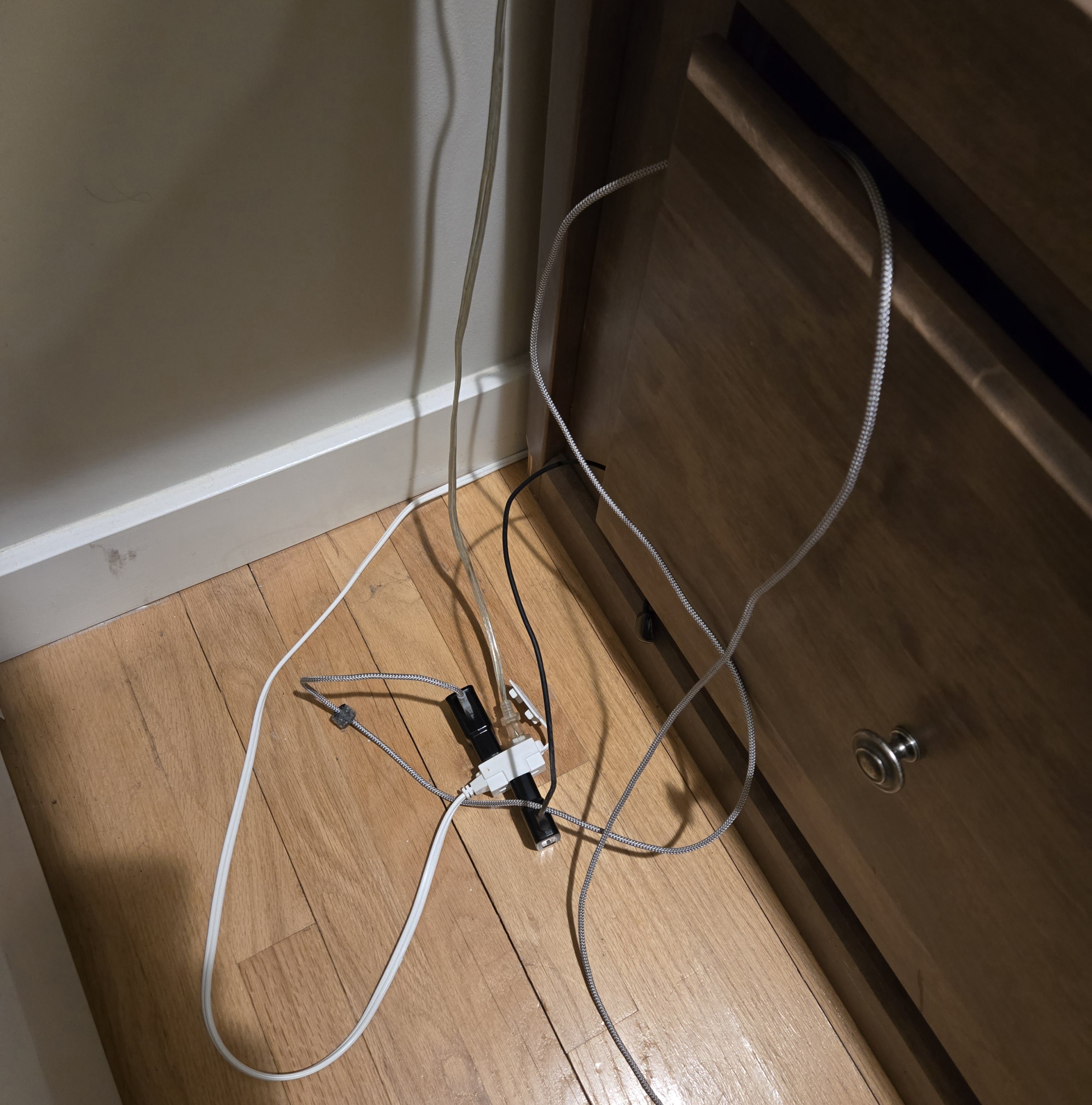
Under my bed are storage drawers where I store my clothes and other items, and next to one of these drawers is an extension cord that I use to charge my devices. These various cables always end up getting trapped in the drawer, causing them to break and fray. My goal is to make a cable organizer that I can stick to my wall to prevent the wires from getting stuck in the drawer.
Looking for a Solution
My first step was to find an already-made 3D model I could print to solve my problem. On Thingiverse, I found this model, which met most of my requirements. However, because it was an .stl file, I had trouble figuring out the dimensions of things, and I wanted to challenge myself by making a piece that had an opening in the center to allow cables to pass through and cable 'clips' at the top.
Initial Model and Sketch
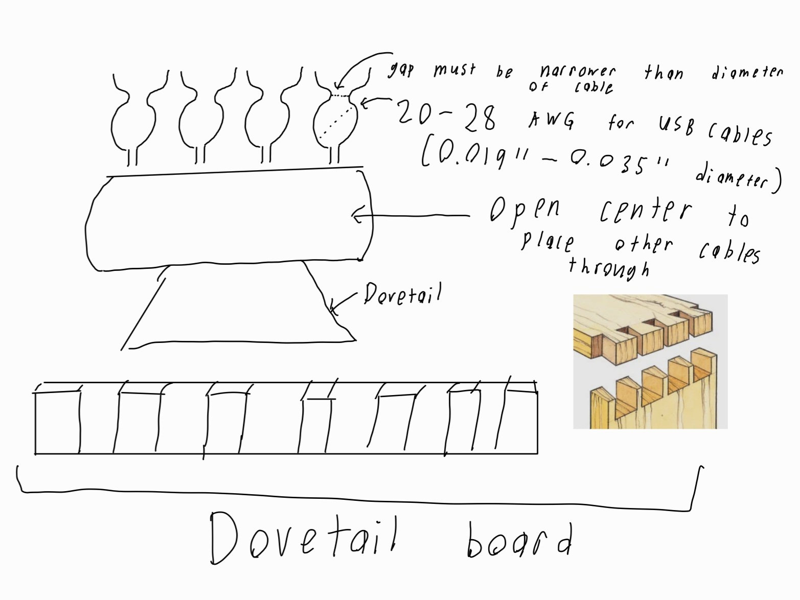
Below is an initial sketch of what I want.
Setup on Tinkercad
After sketching and getting a basic idea of what I wanted to remix about the initial design, I attempted to import the initial .stl file into Tinkercad. This is where I ran into my first roadblock. The .stl file I had was too large to be uploaded to Tinkercad directly. To fix this, I uploaded the file into Meshlab to reduce the number of vertices and faces in the file, thus reducing its size.
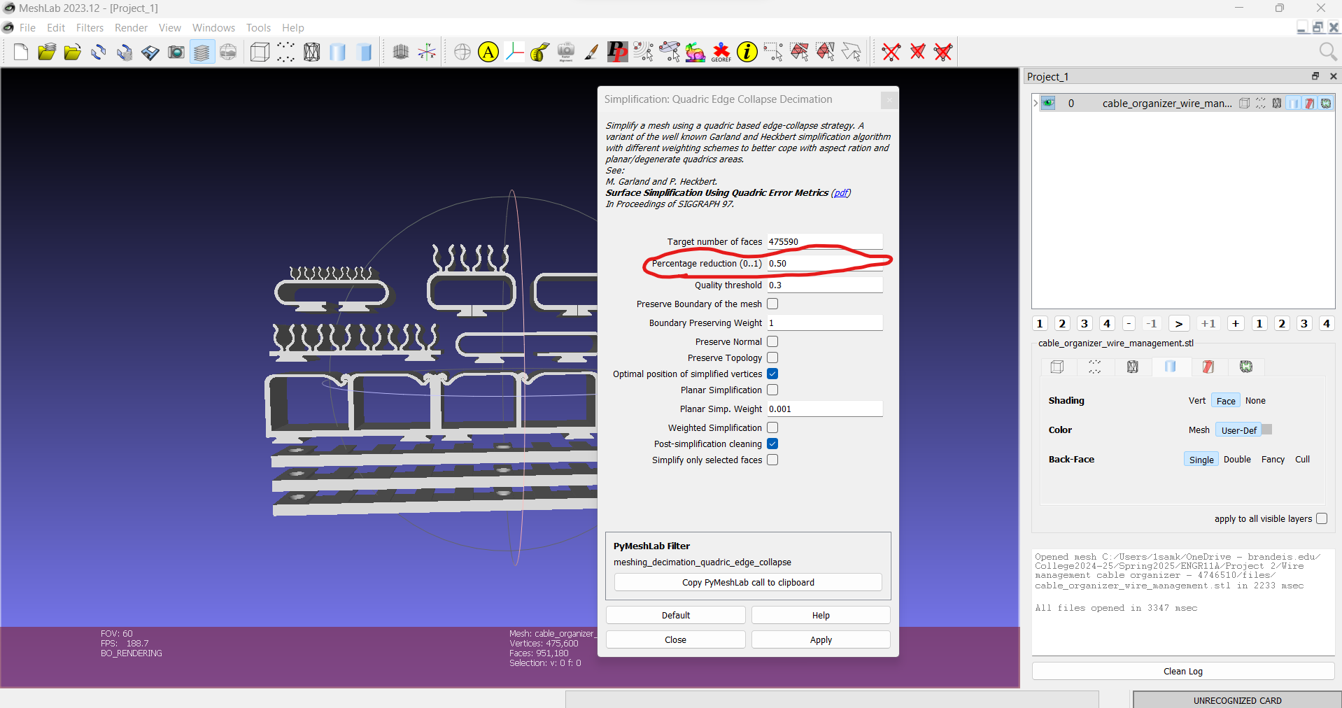
I cut the number of faces in half, which was enough to allow me to upload the model into Tinkercad.
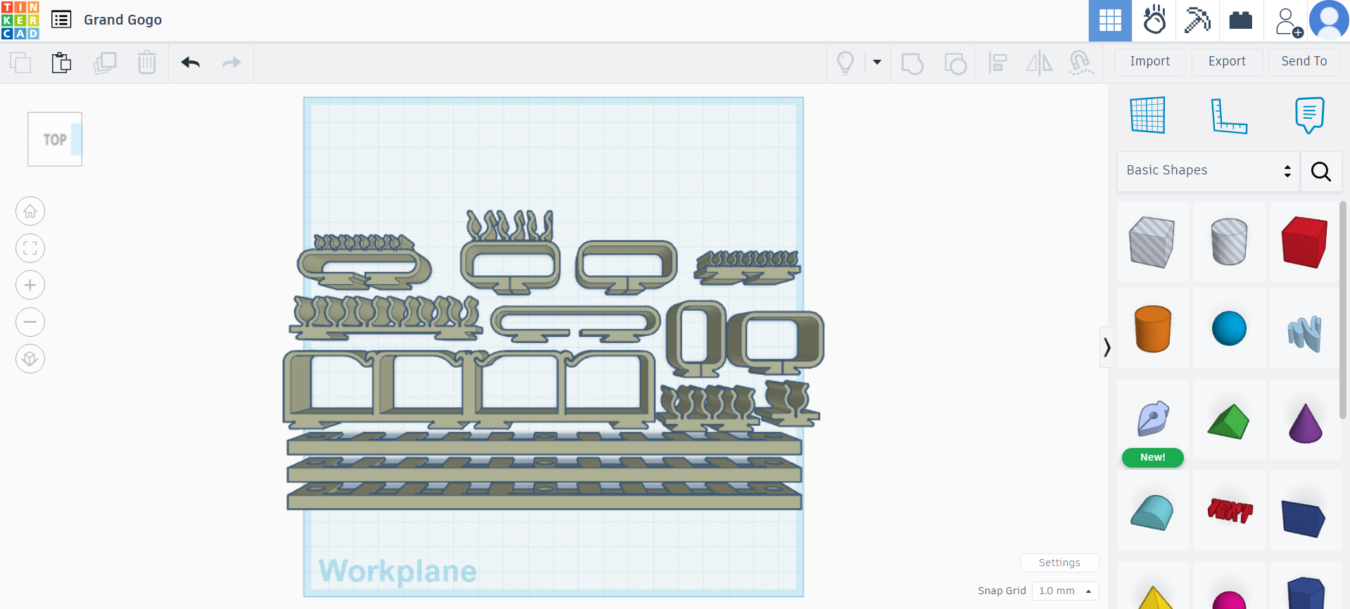
The next task was to edit the pieces of the organizer to fit my specifications. I wanted a piece that had an opening and a few small clips to put cables into. While the design already had some components like this, I wanted to create my own.
Editing the Model on Tinkercad
This process was a huge pain. When uploading to Tinkercad, all the individual pieces of the model were grouped together, and in Tinkercad, there is no easy way to separate them. Therefore, I followed this tutorial to split the objects into individual pieces. After doing this, I combined one of the pieces without a center hole with one of the pieces that had just a center hole. You can see the result here.
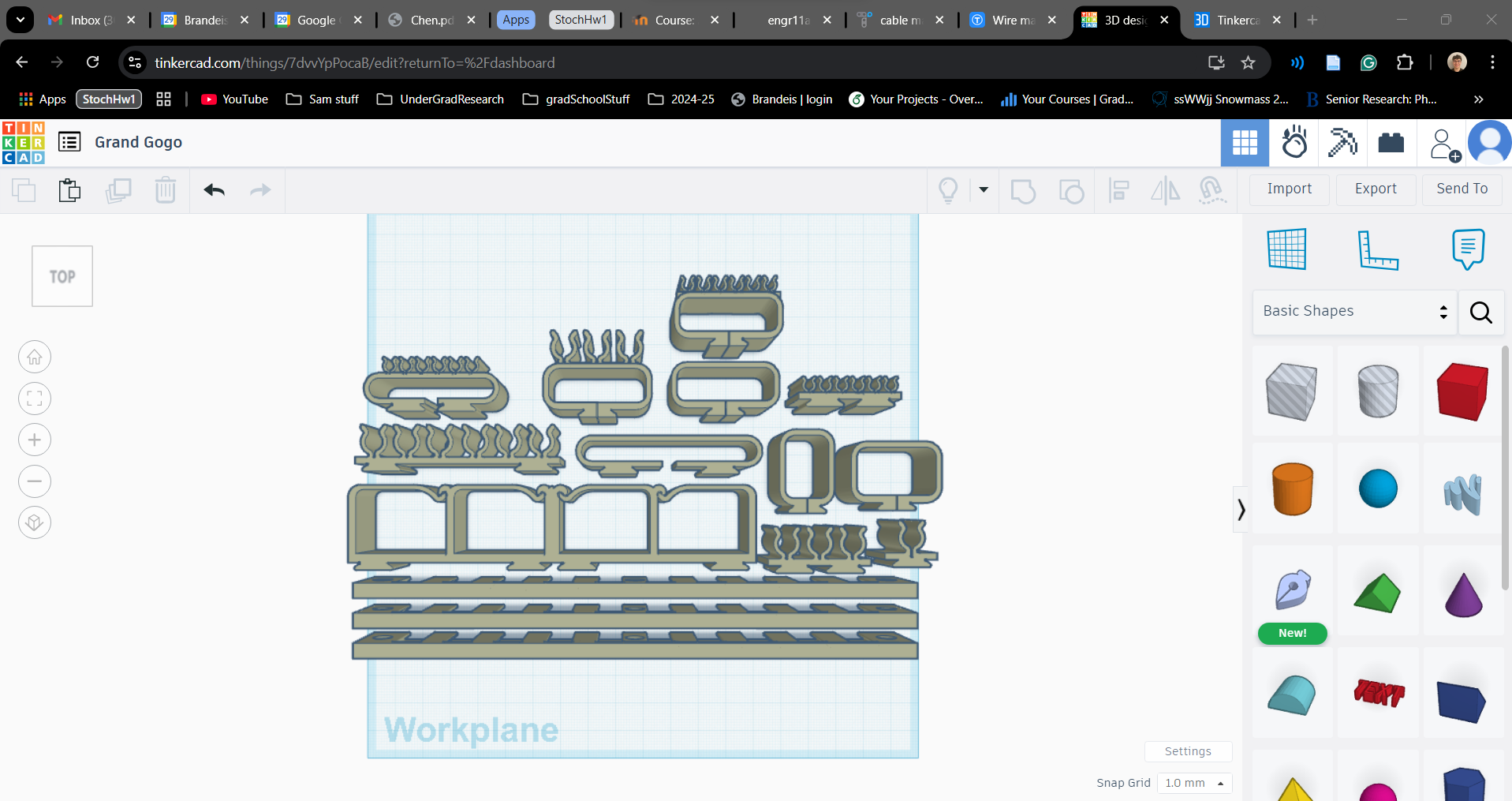
I then exported the result and proceeded to Prusa Slicer.
Printing
Within Prusa Slicer, I had to scale the model to fit the print bed (this would cause problems later). Additionally, to avoid bed adhesion problems, I added rafts to the model. Here are pictures of the before and after slicing along with the print settings.
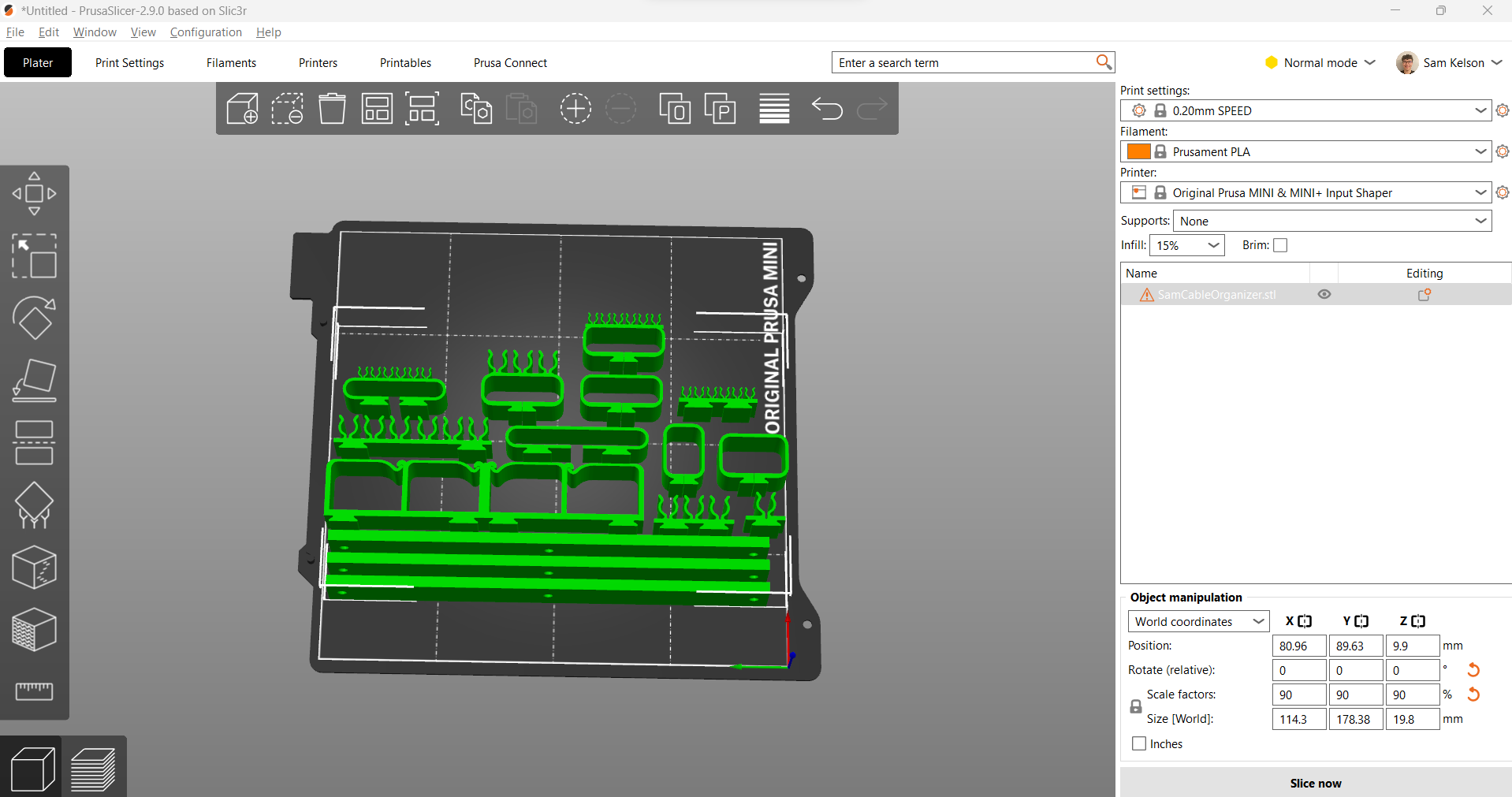
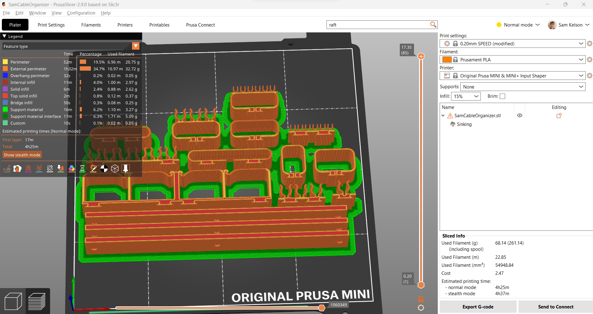
Then, I began the print process.
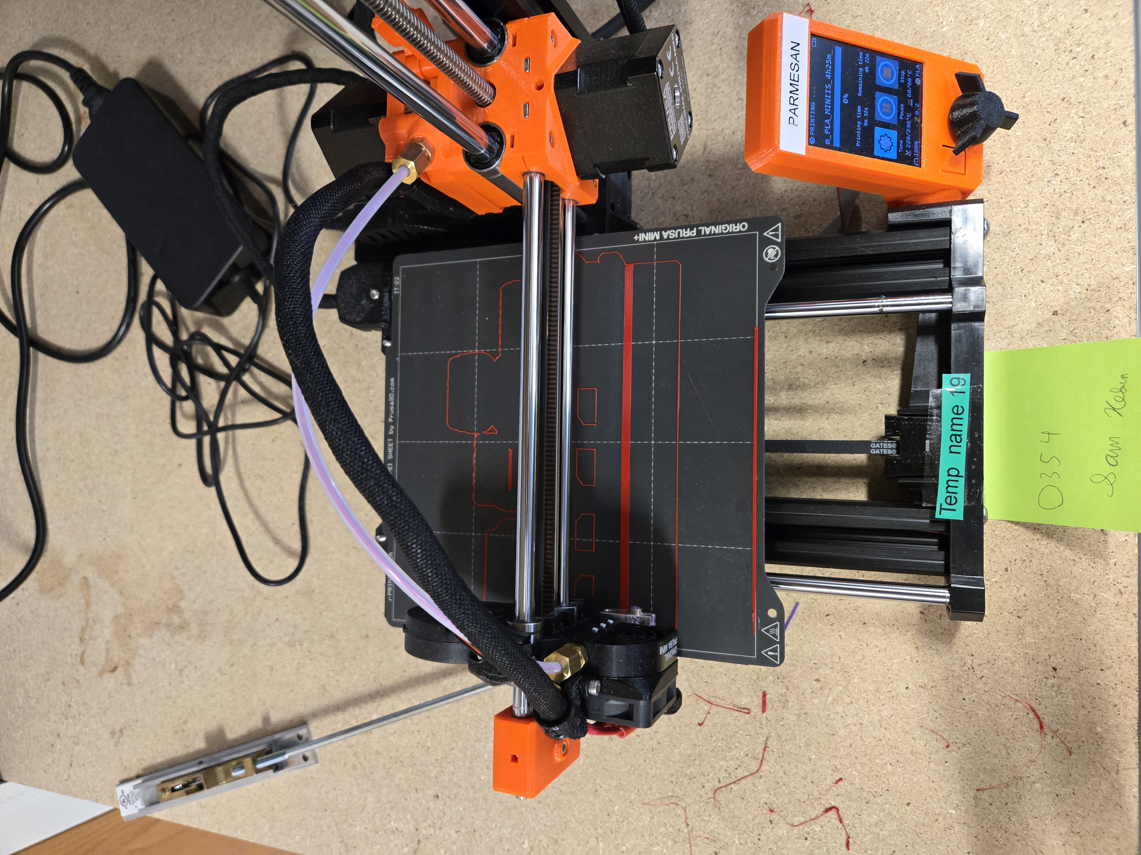
Result and Reflection
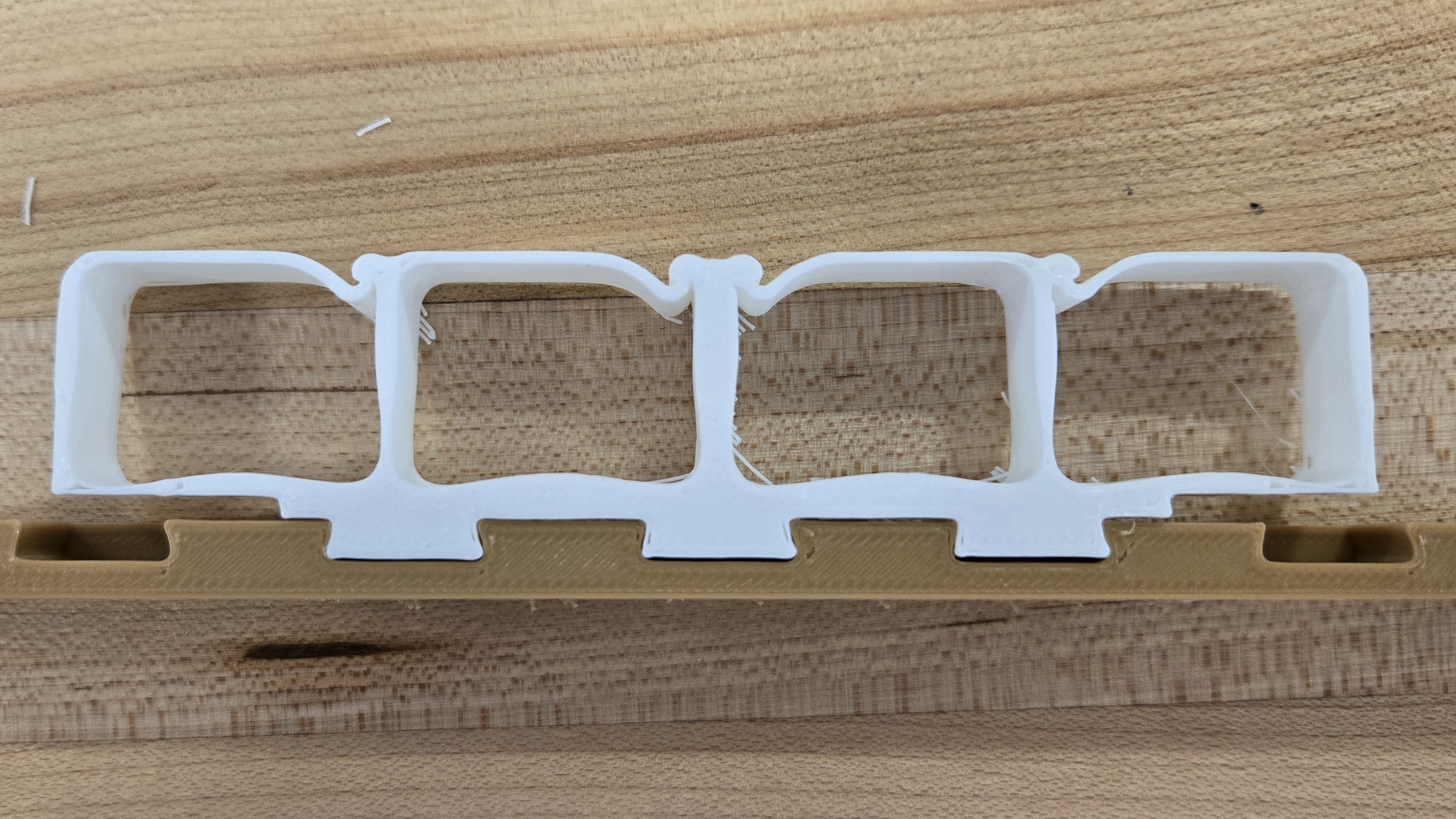
The results were a bit hit or miss. The main problem I found was that the tolerances of the dovetails were not enough to account for the resolution of the printer and the thermal expansion of the filament. As seen in this photo, the dovetails did not fit.
Additionally, as seen in the result photo above, the scaling I did in Prusa Slicer caused the cable clips to shrink dramatically, making them thinner and easier to snap off, along with the radius of the clips being too small to fit any useful cables. Other than that, things were mostly successful. To improve on some of these problems, it would be necessary to closely monitor the dimensions of all these components, especially the dovetails.
Now for an attempt in Autodesk Fusion.
Learning Autodesk Fusion
Before attempting the cable organizer in Fusion, I first went through this series of tutorials. Through these tutorials, I began to really enjoy 3D modeling. While it was a bit challenging, I found myself excitedly completing the entire tutorial—CAD is fun!
Attempting to Import into Autodesk Fusion
This is where the real challenge began. After importing the .stl file into Fusion, I quickly realized that the object was imported as a mesh rather than as bodies. This happened because .stl files store meshes instead of bodies. Therefore, in order to work in Fusion, I needed to convert the meshes into bodies.
This is easier said than done. While there are tools for this, they did not work very well for me. After using some of Fusion’s mesh tools to split up each piece into its individual mesh, I had to project the components onto a flat plane (sketch) and rebuild everything from scratch—resketching and extruding where necessary to create editable objects.
I also decided to delete the dovetails and remake them myself so I could add spacing to account for the unknown tolerances of the printer. Here is an image of the sketch from the projection before removing the old dovetails. A keen observer would notice that none of the lines here are actual Fusion-editable shapes; instead, they are custom geometries, meaning I have no control over their shapes (besides basic scaling) unless I fully redraw them using native Fusion shapes.
Making the Dovetails
I followed these two tutorials (Make or Break Shop and Product Design Online) for making the dovetails. They both use user-defined parameters, which I find to be an amazing feature of Fusion. This allowed me to follow the tutorials without worrying about dimensions until I had finished the setup, making changes super easy.
I also added a parameter to control an extra extrusion that created a controllable gap between the pin and socket of the dovetail.
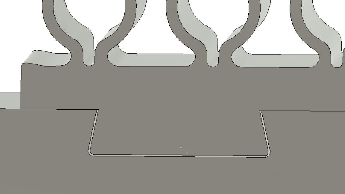
I initially set this parameter to 0.02 inches. I then copied the pinboard and attached it to each individual component.
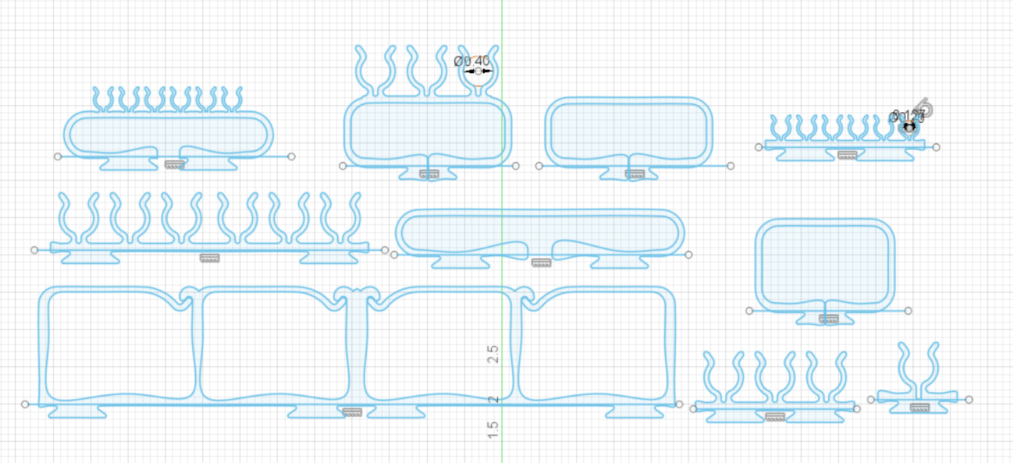
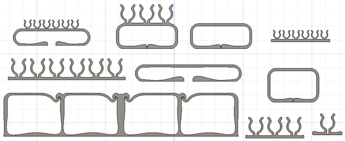
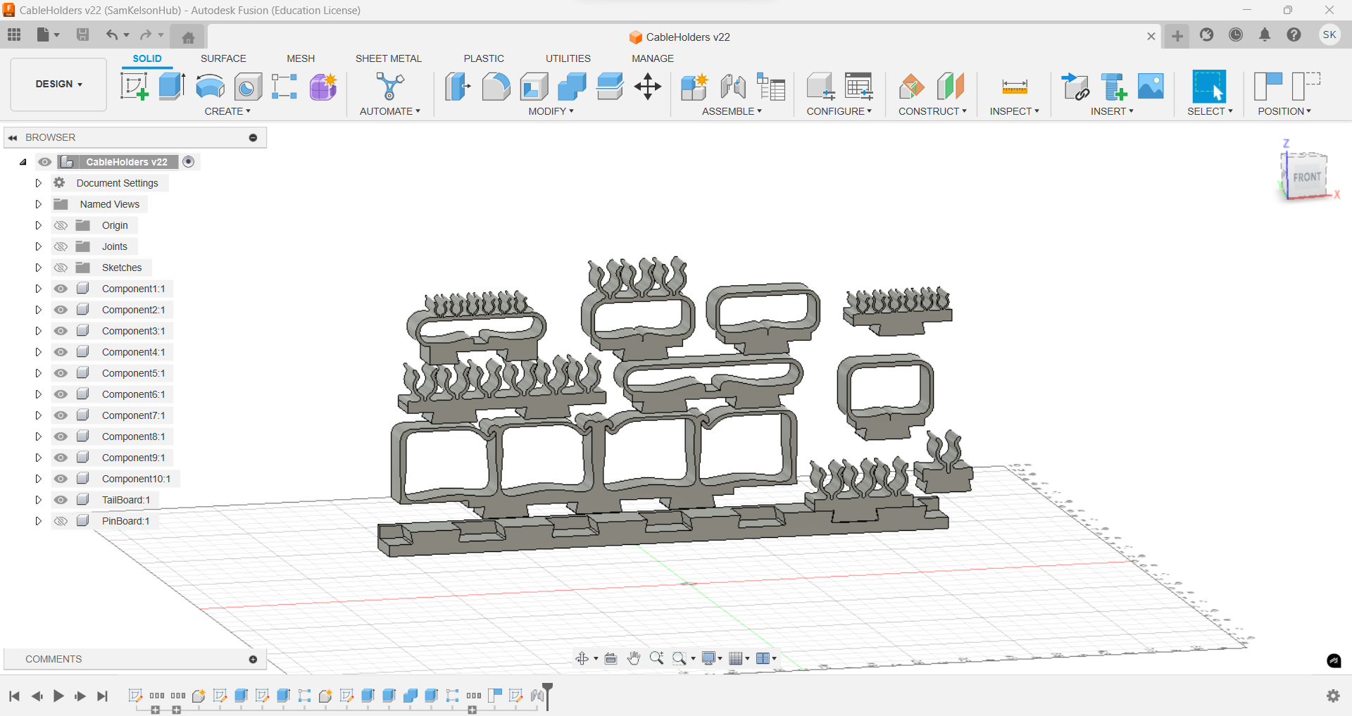
Here is an image of the finished project in Fusion. A lot of steps went into the creation process, including sketching, extruding, and aligning.
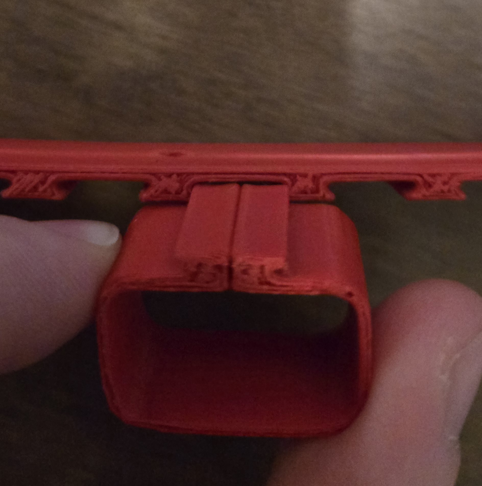
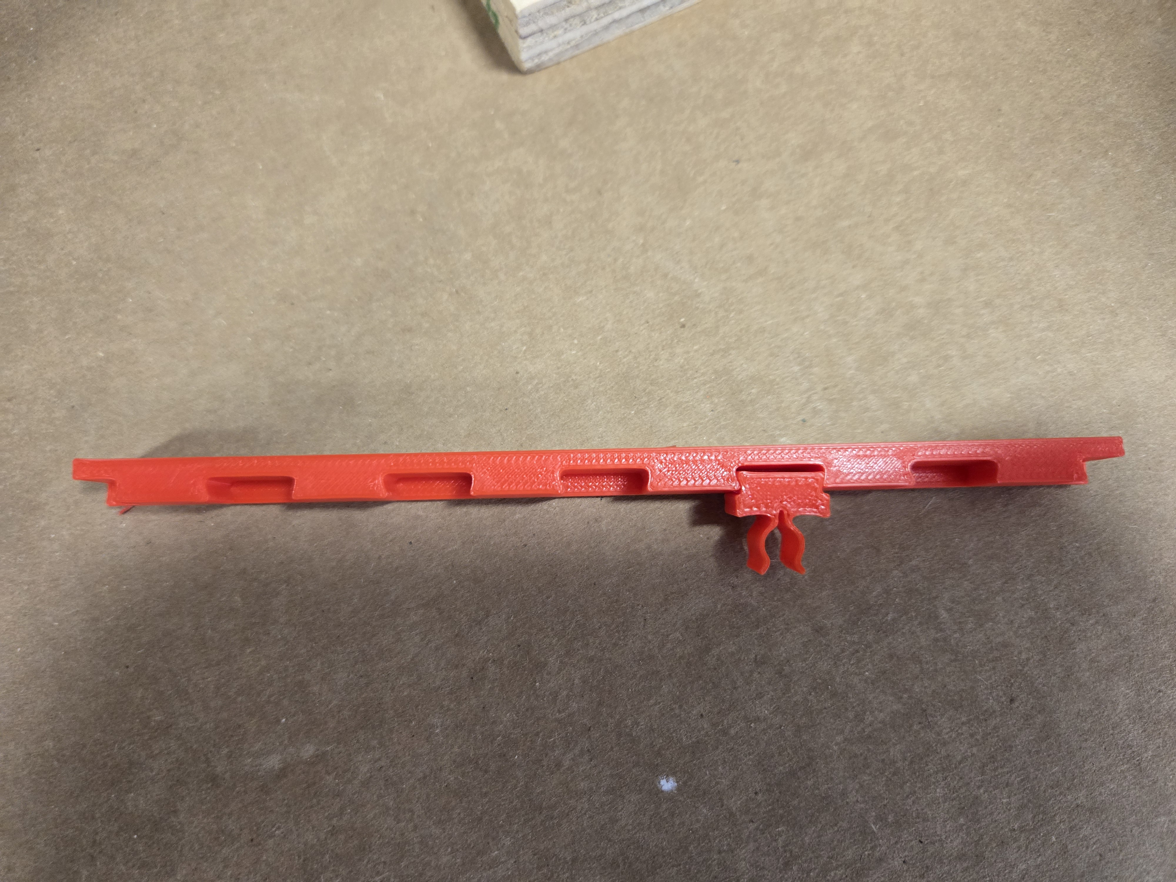
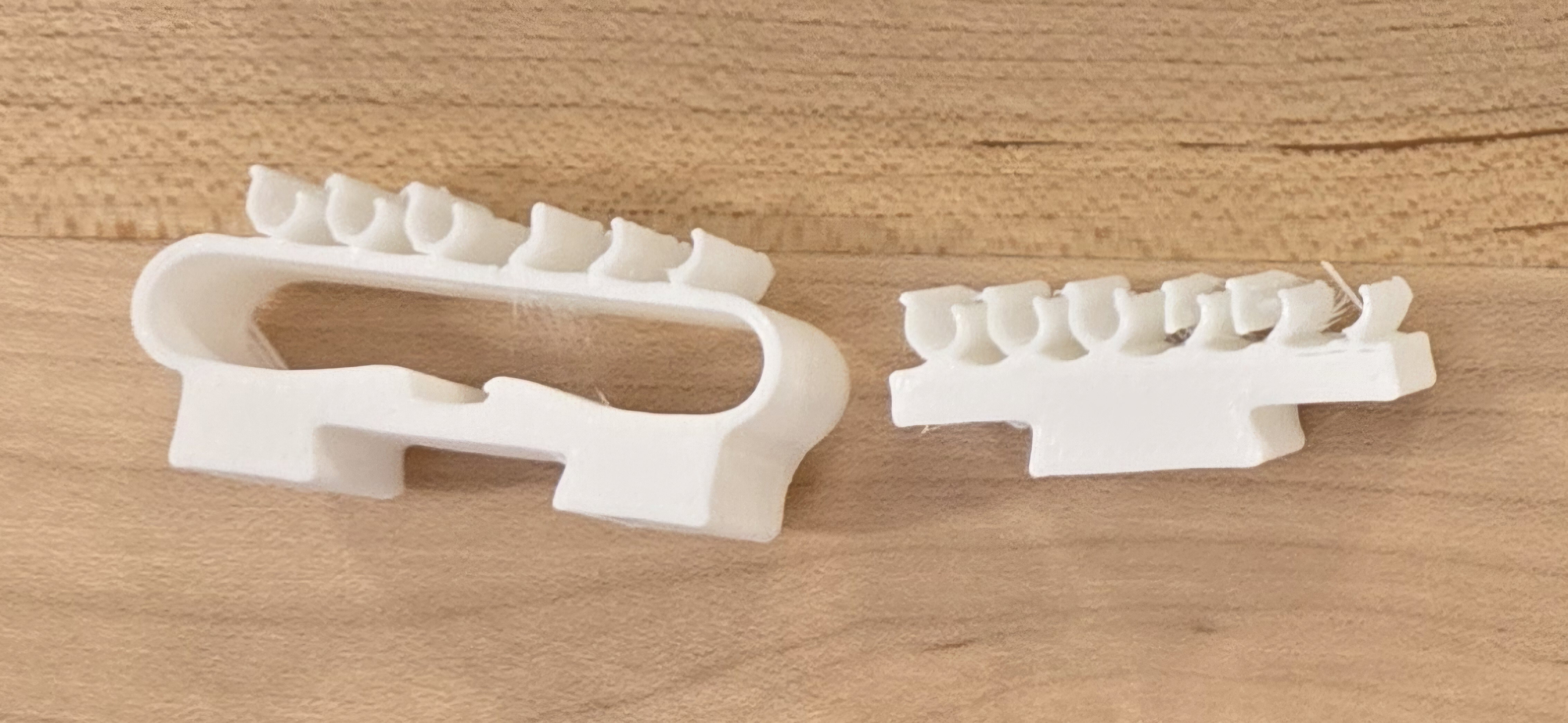
A Test Print
To test the tolerances and make sure everything aligned and fit, I printed a single component and the tailboard (I will show Slicer settings momentarily). Here is the result—you can see that everything fits, albeit a bit loose.
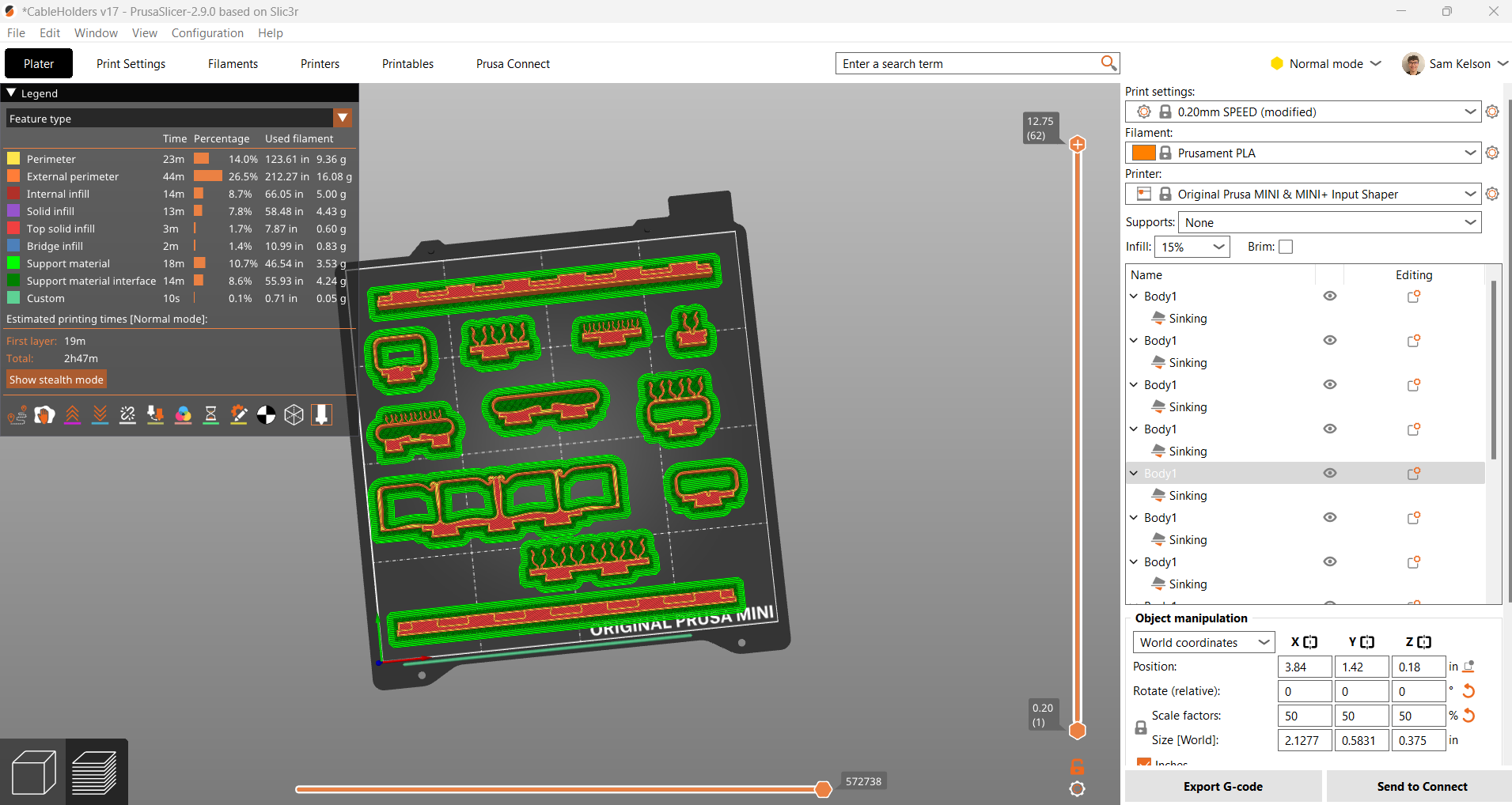
Final Print
Satisfied with the test results, I decided to proceed with the full print. I still had to scale the print down in Prusa Slicer, which I was hoping to avoid, but I did not have time to fix this. One advantage of having the individual components split up was that when importing into Prusa Slicer directly from Fusion, the parts stayed as separate bodies, allowing me to arrange them in Prusa Slicer.
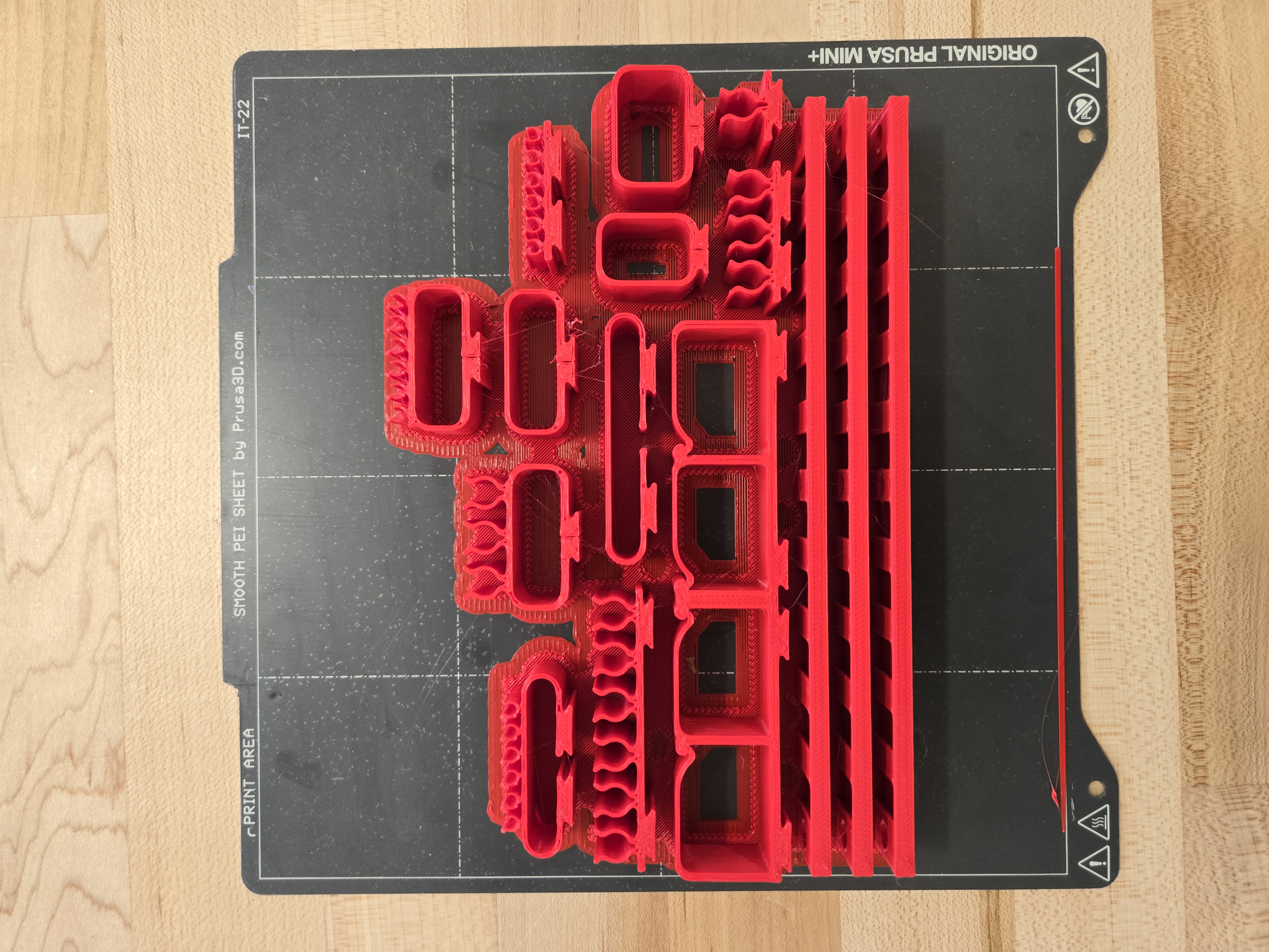
Final Result
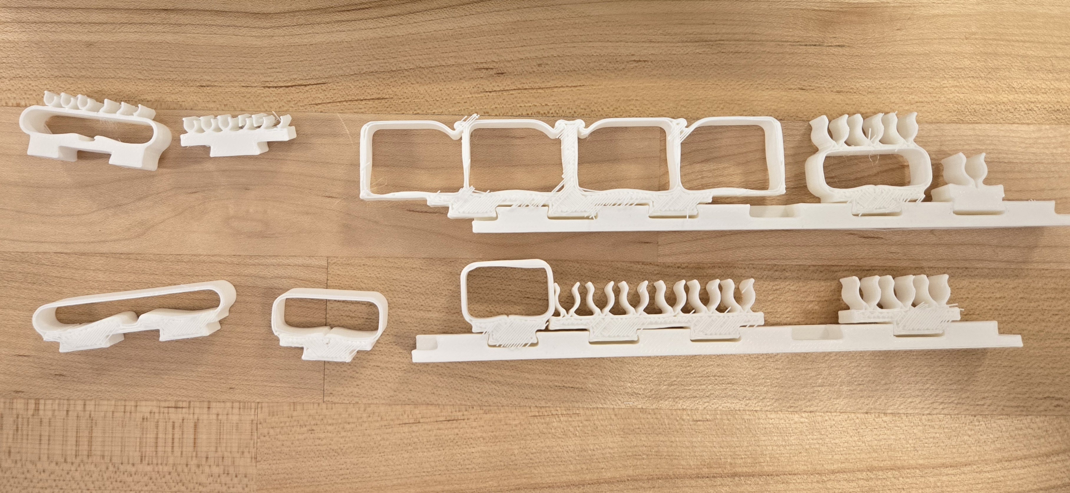
Above is the final result, and everything looks pretty good. The only issue was again due to scaling, where some of the pieces became too thin and brittle. Additionally, it was hard to judge which cables would fit into the clips. I will likely end up using the pieces with the open middle the most, as those came out the best.
An Extra Tolerance Test
After my final print, I became a bit wary of the dovetails being too loose and wanted to lower the tolerances before reprinting. While not intentional, the way I designed the tolerance meant I only needed to reprint the tailboard, which saved both plastic and time. After reprinting, I was much happier with the tolerance level.
Overall Thoughts
Overall, I achieved my goal of creating a cable organizer, but the process revealed areas for improvement. The time I spent converting the mesh to a body could have been better used to redesign and redraw the parts from scratch, making it easier to precisely specify the diameter of the cable clips.
I also gained a deeper appreciation for Fusion’s parametric design approach—the ability to revisit previous steps in the timeline, make modifications, and have all subsequent steps update accordingly is incredibly convenient. In the future, I would refine my initial concept and recreate the design entirely in Fusion to improve adaptability and allow for easier modifications.