ENGR11a: Robotic Tracking Car Enclosure
Introduction
This project introduced the fundamentals of electronics prototyping, integrating soldering, component assembly, and iterative design. Working in a team, we designed and fabricated a custom chassis enclosure for a robotic tracking car, focusing on form, fit, and function through multiple design iterations. Using Autodesk Fusion 360, we developed CAD models and utilized both 3D printing and laser cutting to refine our designs. Key challenges included ensuring accessibility for sensors, wheels, and power components while maintaining the overall fit of the enclosure. This hands-on experience strengthened my skills in rapid prototyping, digital fabrication, and collaborative design.
Robot Assembly
For the first stage, my group assembled individual D2-5 Intelligent Tracking Car DIY kit robots following these instructions. The instruction manual included helpful visuals, making it easier to understand part placement. However, the drive shaft assembly section was unclear, particularly regarding the worm gear's fit, which later became an issue.
The process began with soldering, a skill I was familiar with but was new for some of my teammates. With occasional guidance, everyone successfully soldered their circuit boards.
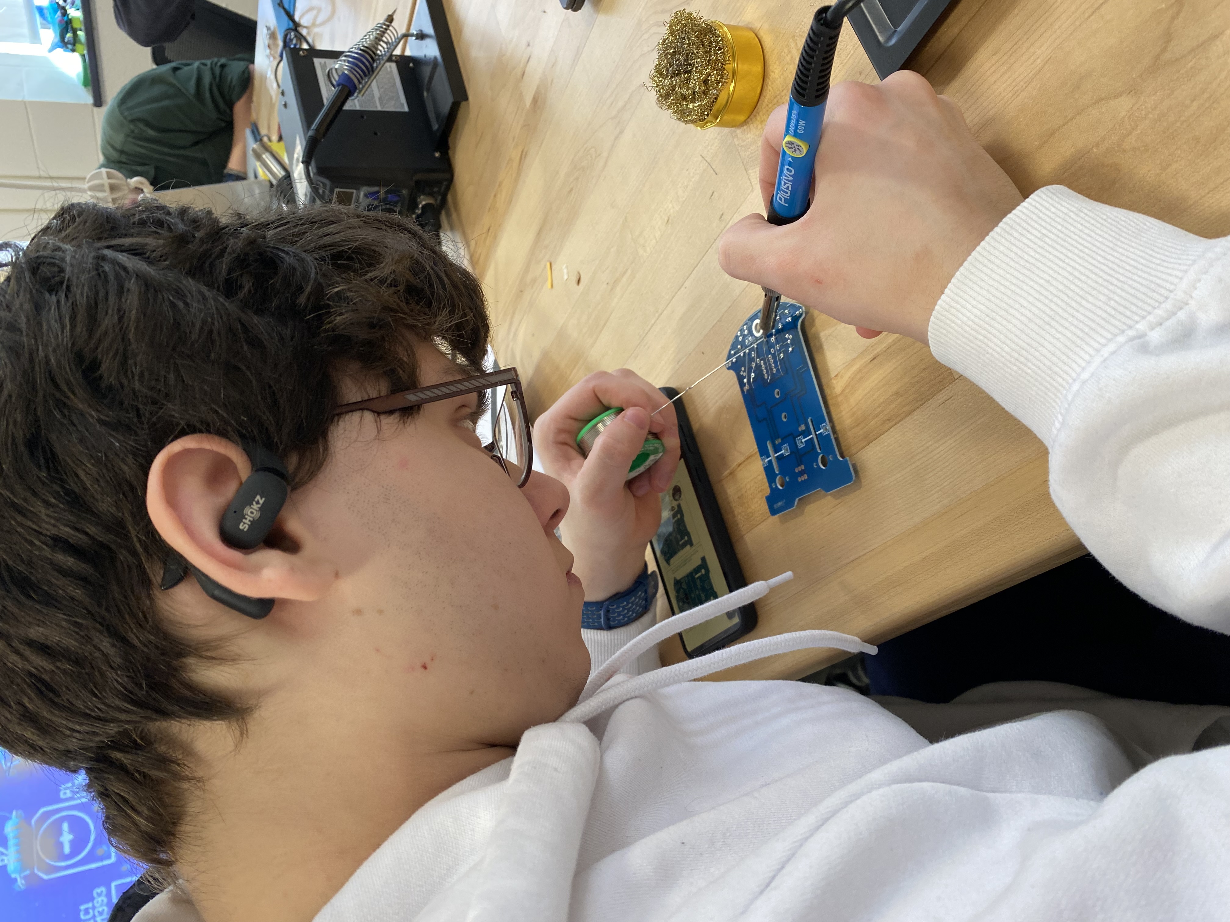
The main challenge in electronic assembly was ensuring all components were correctly oriented, particularly LEDs, capacitors, and transistors. Additionally, some soldering iron tips performed better than others, and setting the correct temperature was tricky. The most critical challenge, even for experienced solderers, was avoiding excessive heat application, which could detach solder pads from the PCB.
When I first powered my car, I noticed that one of the LEDs was not working.
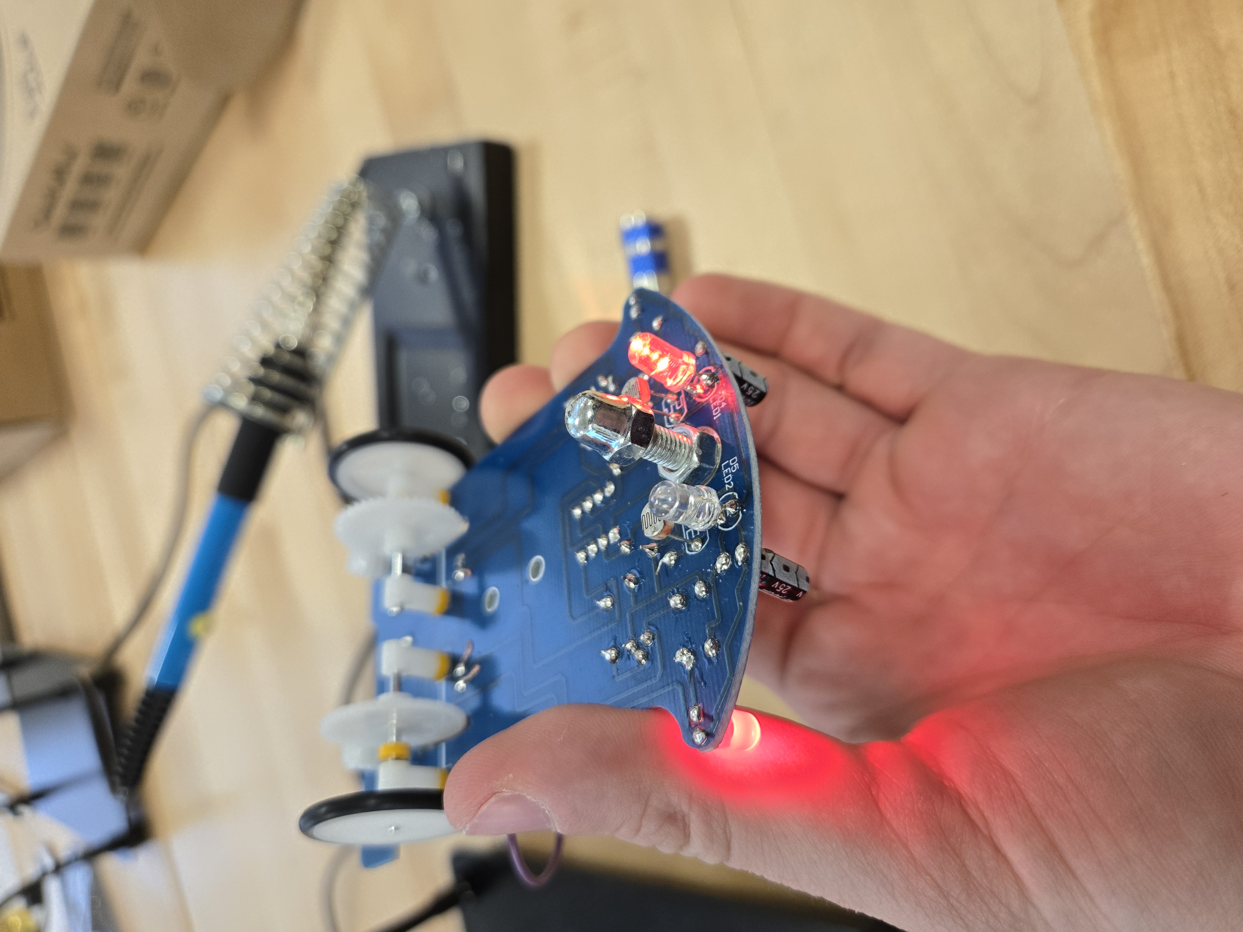
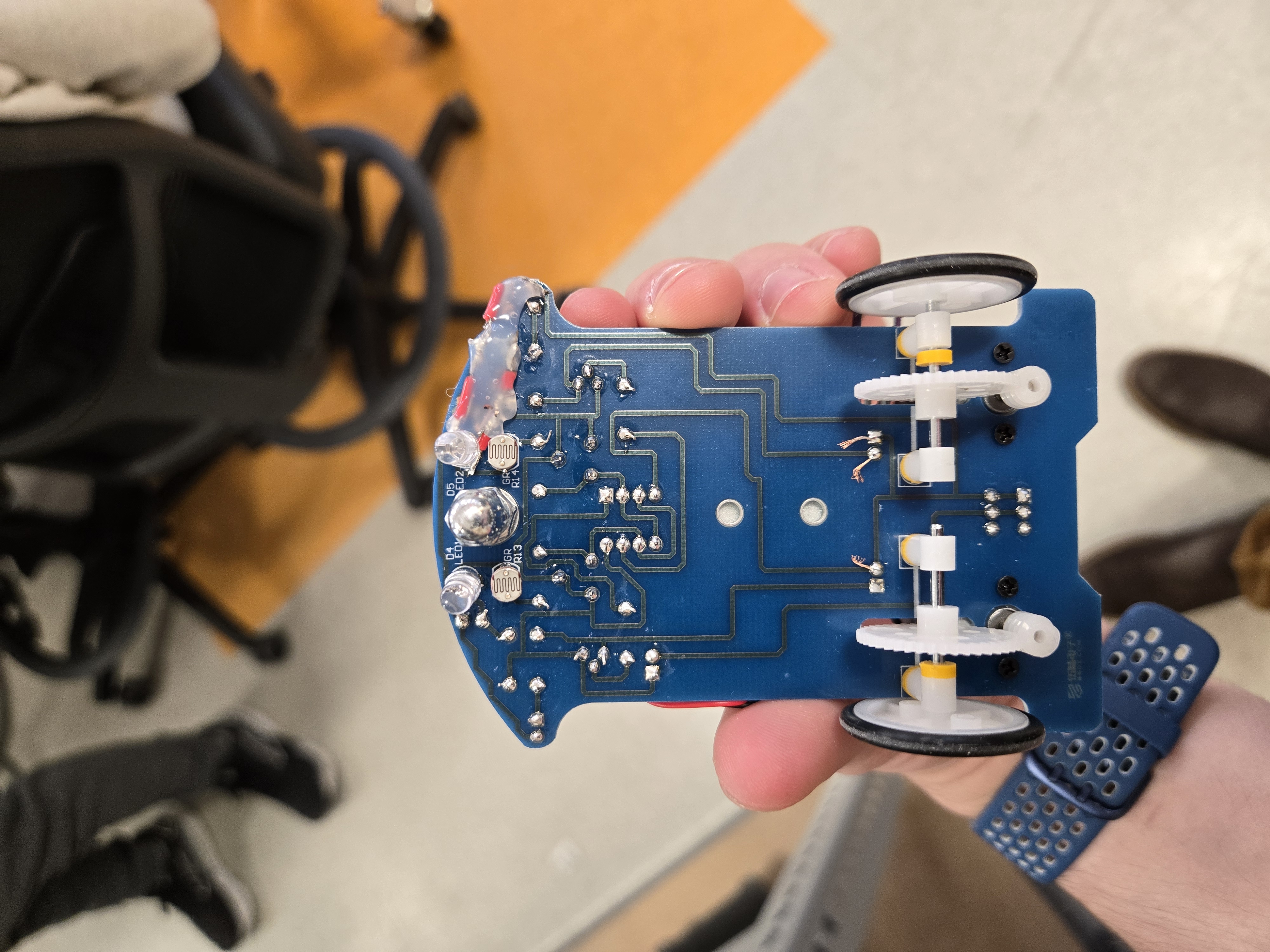
Using a multimeter and an external battery, I identified a faulty capacitor disrupting the circuit. While attempting to replace it, I accidentally desoldered both capacitor pads, seemingly ruining the board. However, by analyzing the circuit diagram, I bypassed the capacitor with wires, restoring functionality. To prevent accidental contact, I secured the fix with hot glue.
The final challenge was ensuring proper engagement between the worm gear and wheel axle. The instruction manual lacked sufficient guidance on this step. Proper torque transfer required careful alignment, which was complicated by play between drivetrain components. The best solution was to tighten the three-way sleeve screws after initial assembly and it would have been nice to add extra gaskets to reduce unwanted movement.
Here’s a video of the car moving along a track:
Measurements
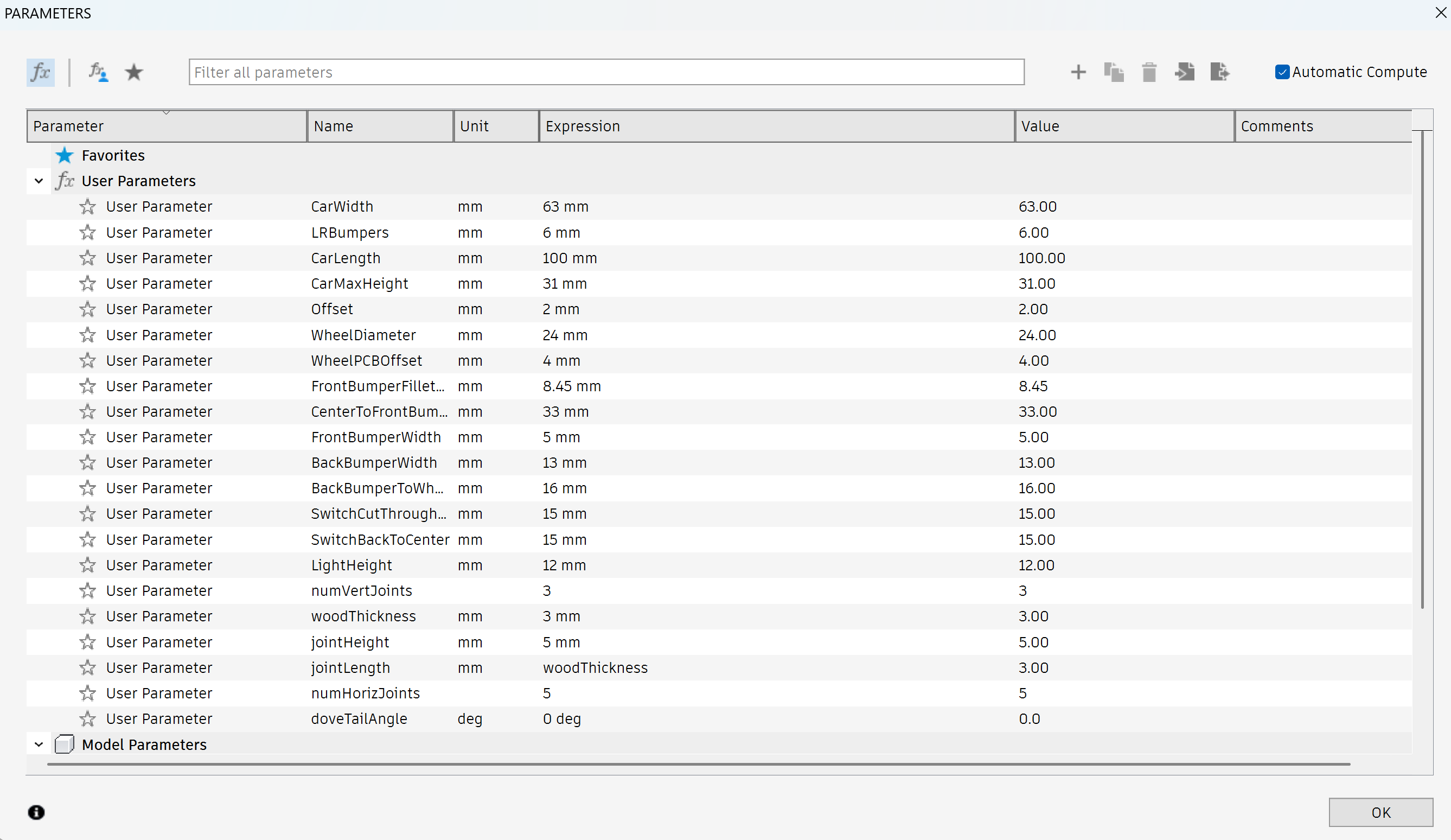
To design the chassis enclosure, we needed precise PCB measurements, which I took using digital calipers.
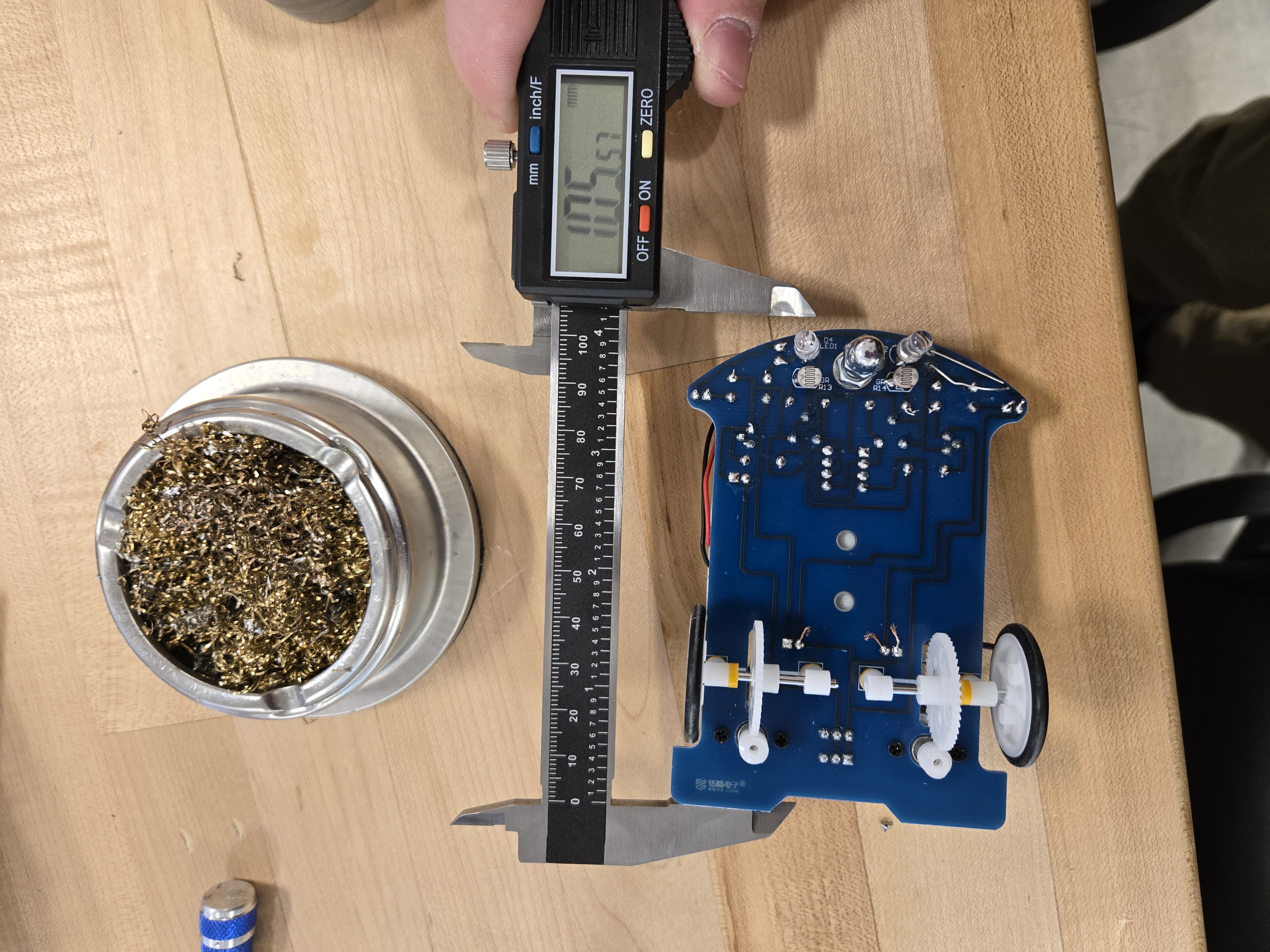
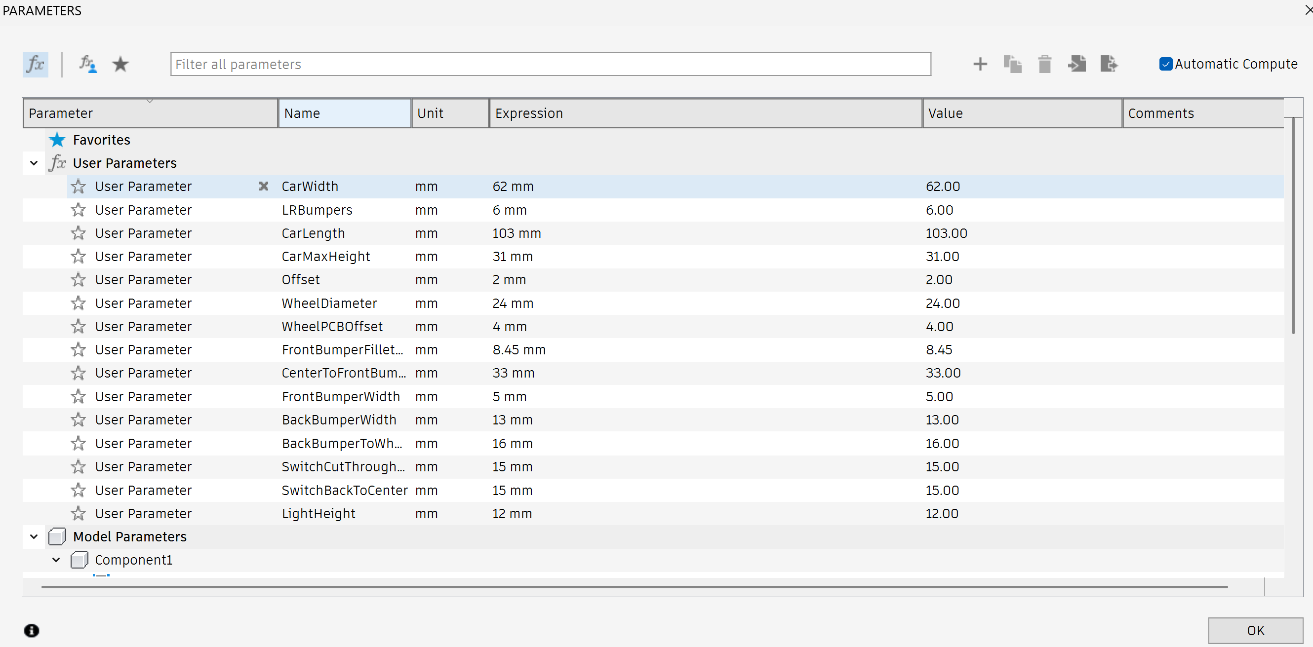
These measurements were then imported into Fusion 360 as parameters.
Designing in Fusion 360
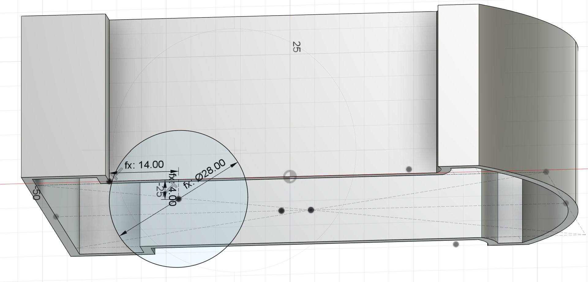
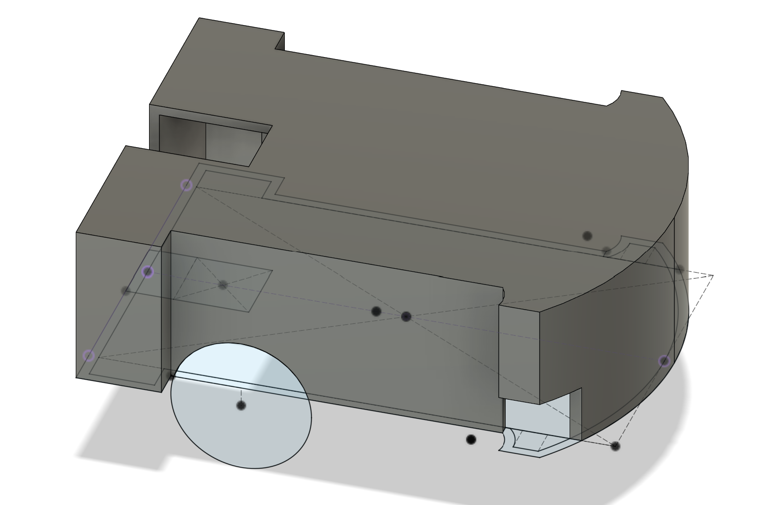
Using these parameters and a reference image of the PCB, I created an initial sketch in Fusion 360.
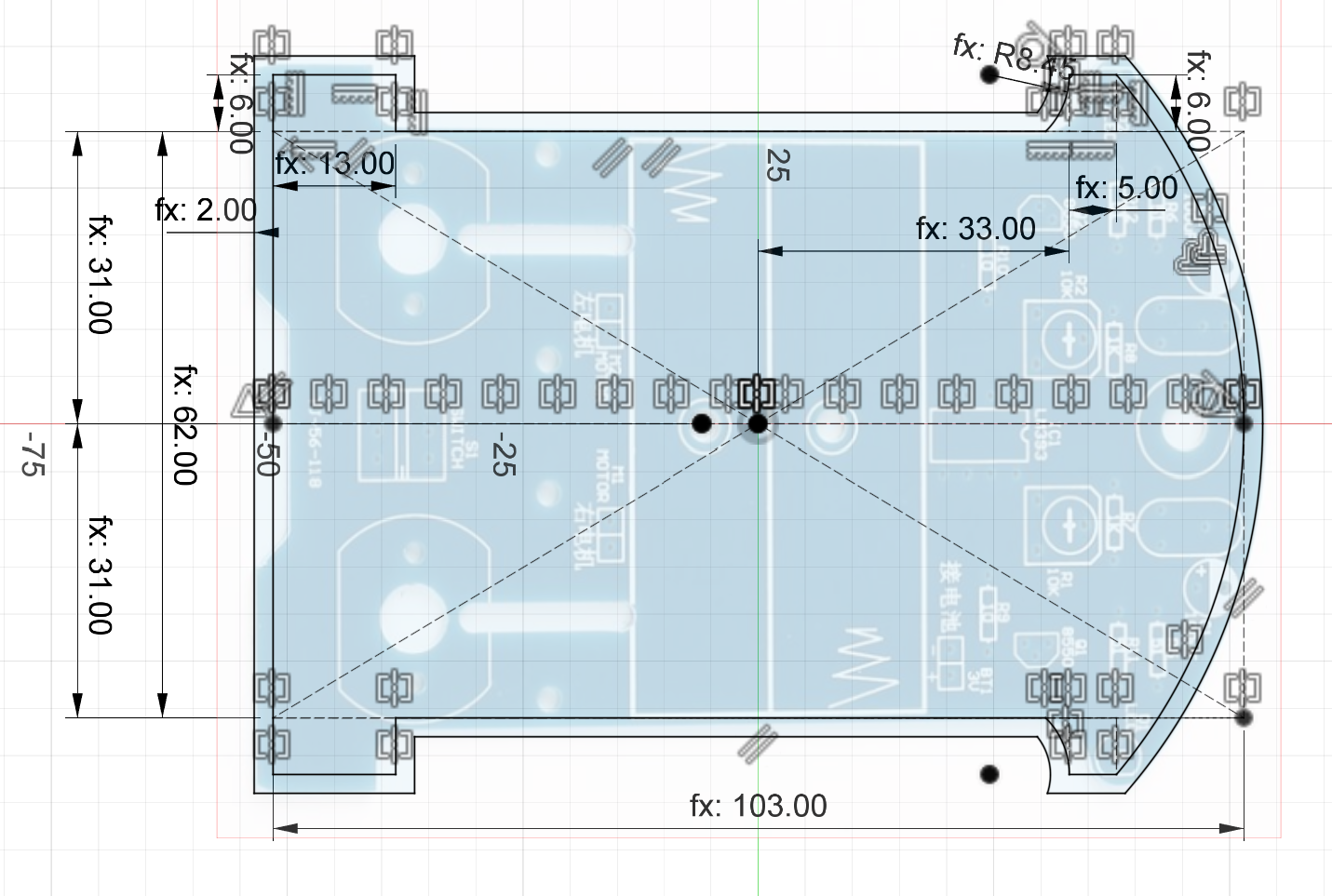
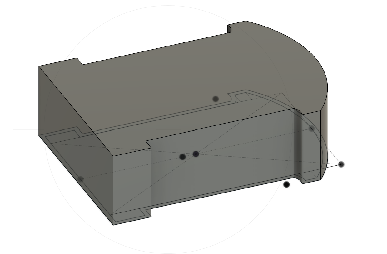
After extruding the sketch, we produced our first 3D model.
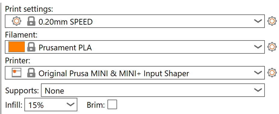
Using default Prusa Slicer settings:
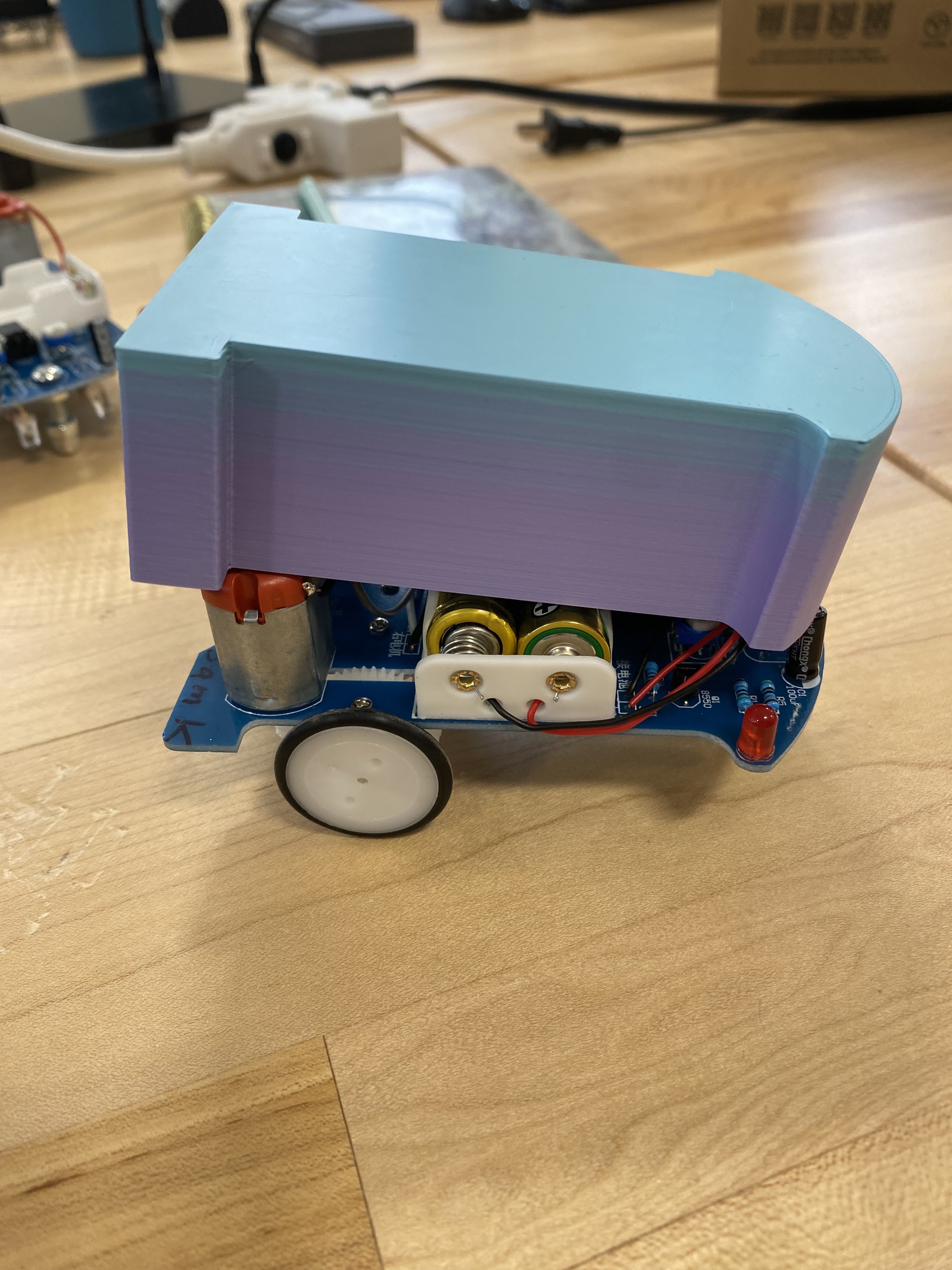
Here’s the first 3D-printed enclosure:
Iterating for Fit
The first enclosure did not fit correctly due to an extrusion direction error, making it too small. This prevented proper testing of component clearances, including LED covers and wheel gaps. For the next iteration, we corrected the extrusion and made additional adjustments.
Although we didn’t document the second iteration with photos, it helped us identify other fit issues, such as wheel interference and inadequate front light clearance.
For the third iteration, we added wheel cutouts and an accessible power switch slot.
Resulting in this improved version:
One persistent challenge was determining the enclosure’s resting position relative to the PCB. Because modifications to the design were made outside of class, iteration cycles were long, making adjustments difficult. Additionally, accounting for 3D printer tolerances and unforeseen measurement needs—such as precise wheel clearances—proved challenging. In hindsight, more upfront measurements would have streamlined the process.
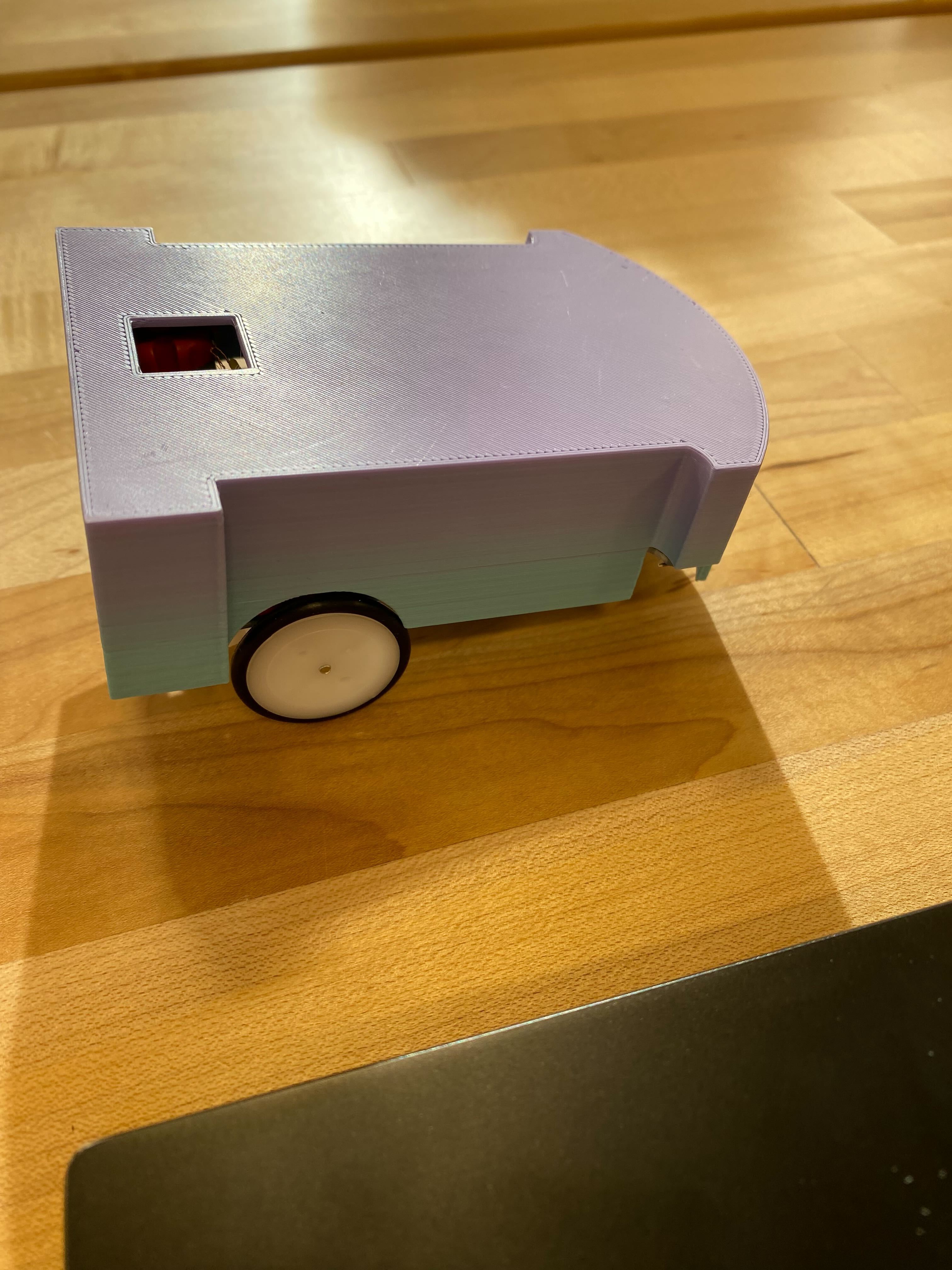
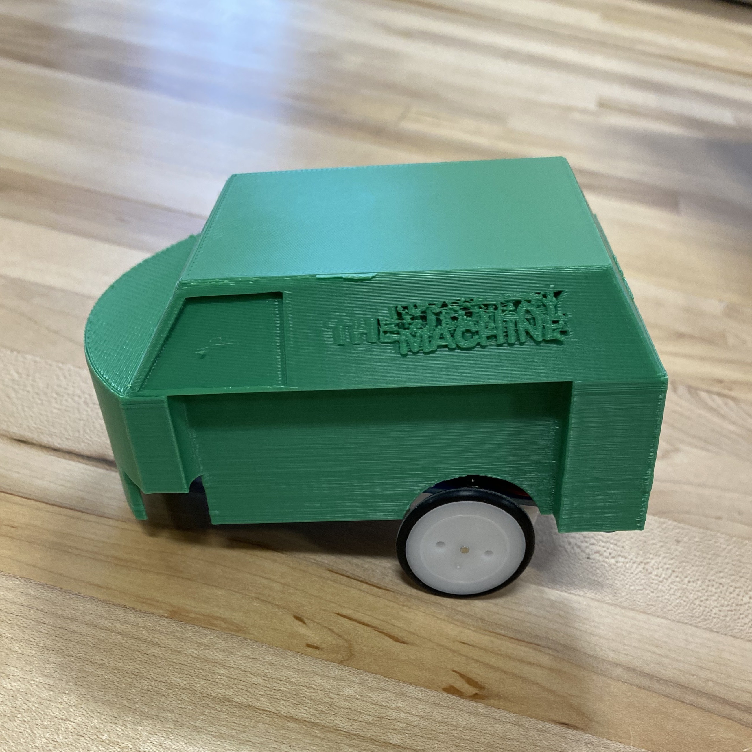
In the final iteration, we added cutouts for the LEDs and extended the switch cutout to improve accessibility.
For aesthetics, we incorporated the Mystery Machine design from Scooby-Doo onto the top of the car.
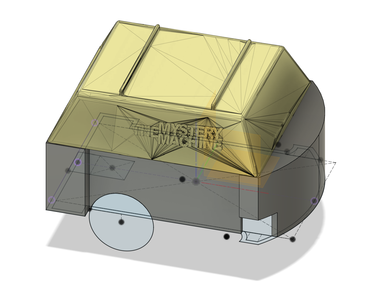
We flipped the model onto the top in Prusa Slicer for faster and more stable printing (something we did throughout) and added build plate supports.
The fit improved, but the enclosure was still slightly too long. One final iteration refined this.
To access the batteries, the enclosure was designed for easy removal. All movement, LED visibility, and switch access requirements were met.
Reflections on 3D Printing
Overall, the 3D printing process was smooth. The main drawback was the slow iteration cycle, which made refining the fit challenging.
Laser Cutting an Enclosure
For the next phase, we designed a laser-cut enclosure, learning the advantages and constraints of this type of subtractive manufacturing.
Following a Fusion 360 dovetail box tutorial, I created a box that would rest on the PCB. I found the assignment’s suggested tutorial inefficient and instead used Fusion 360’s patterning system for faster iteration.
To simplify assembly, I opted for finger joints instead of dovetails by setting the dovetail angle to zero.
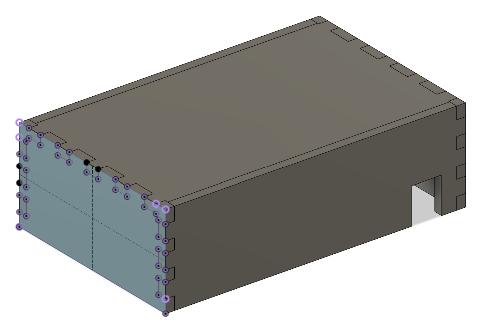
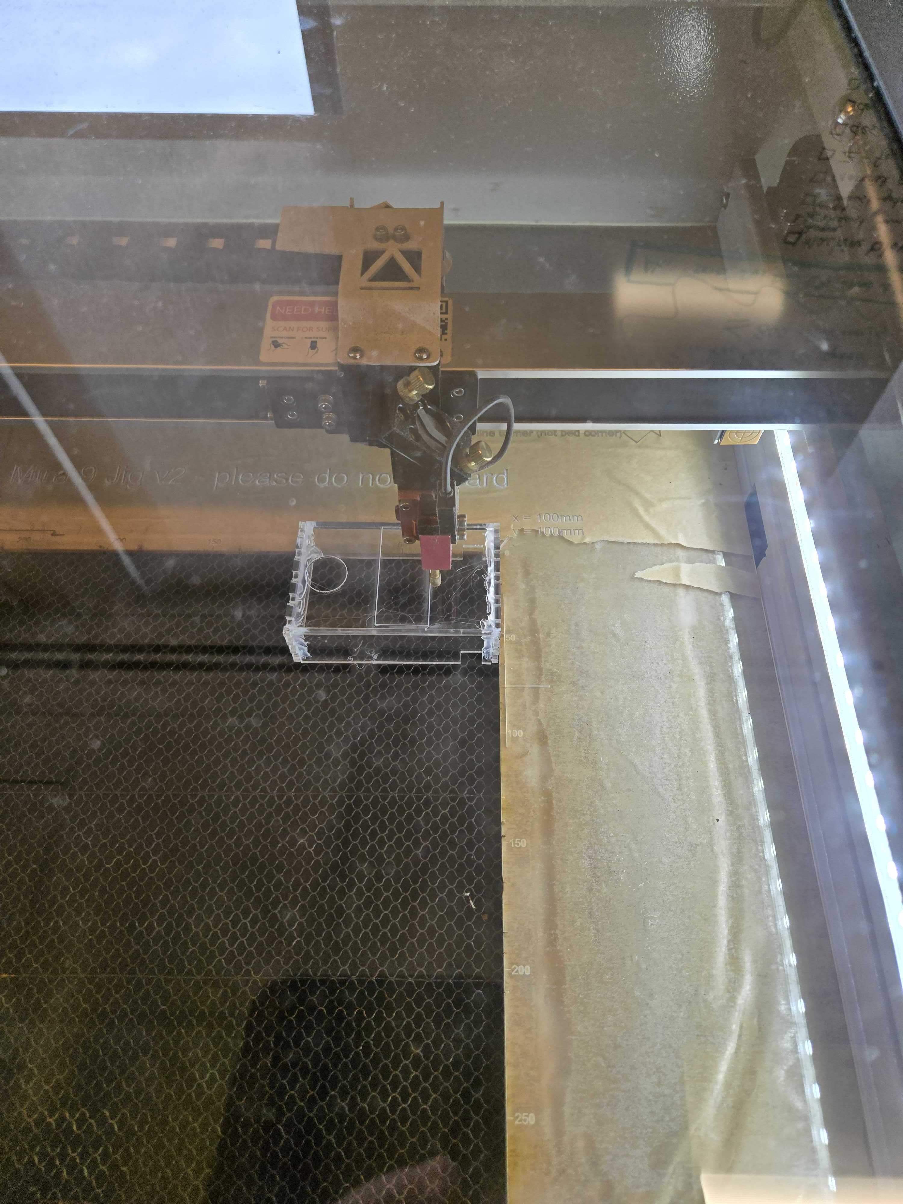
After learning Lightburn and laser cutting procedures, we produced our first prototype.
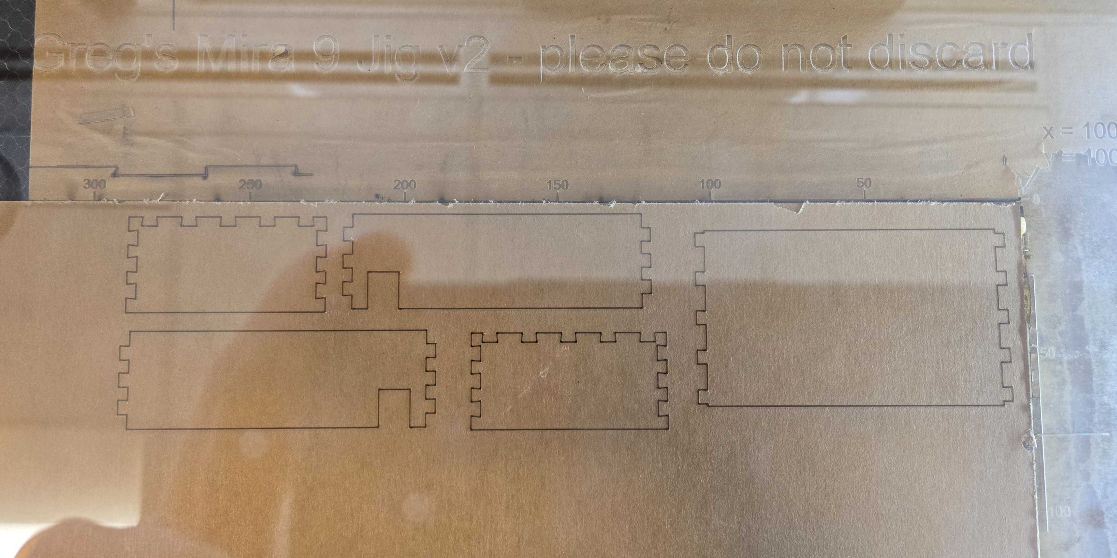
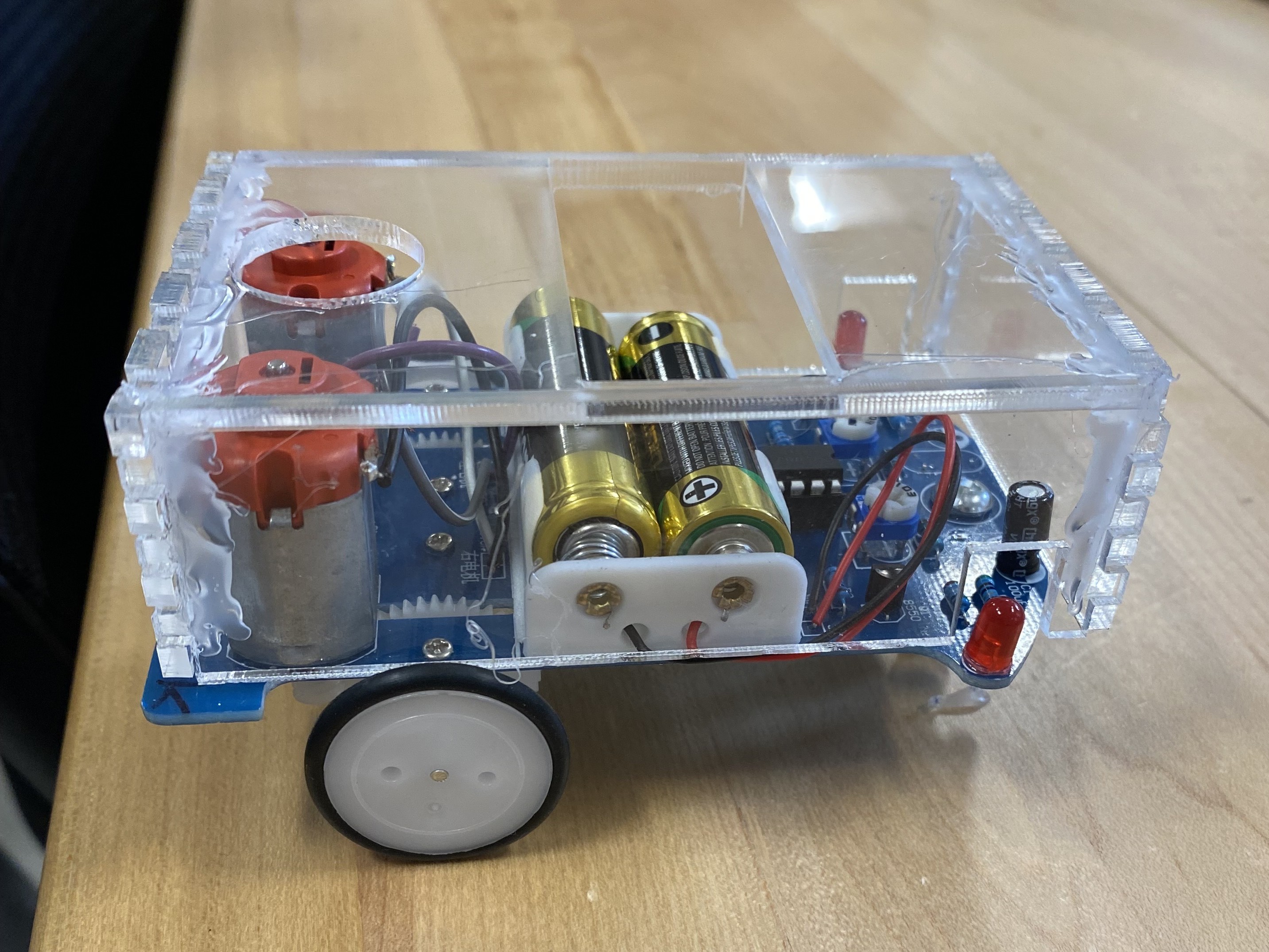
We accidentally printed in Acrylic which while looking nice was a very hard to assemble and glue.
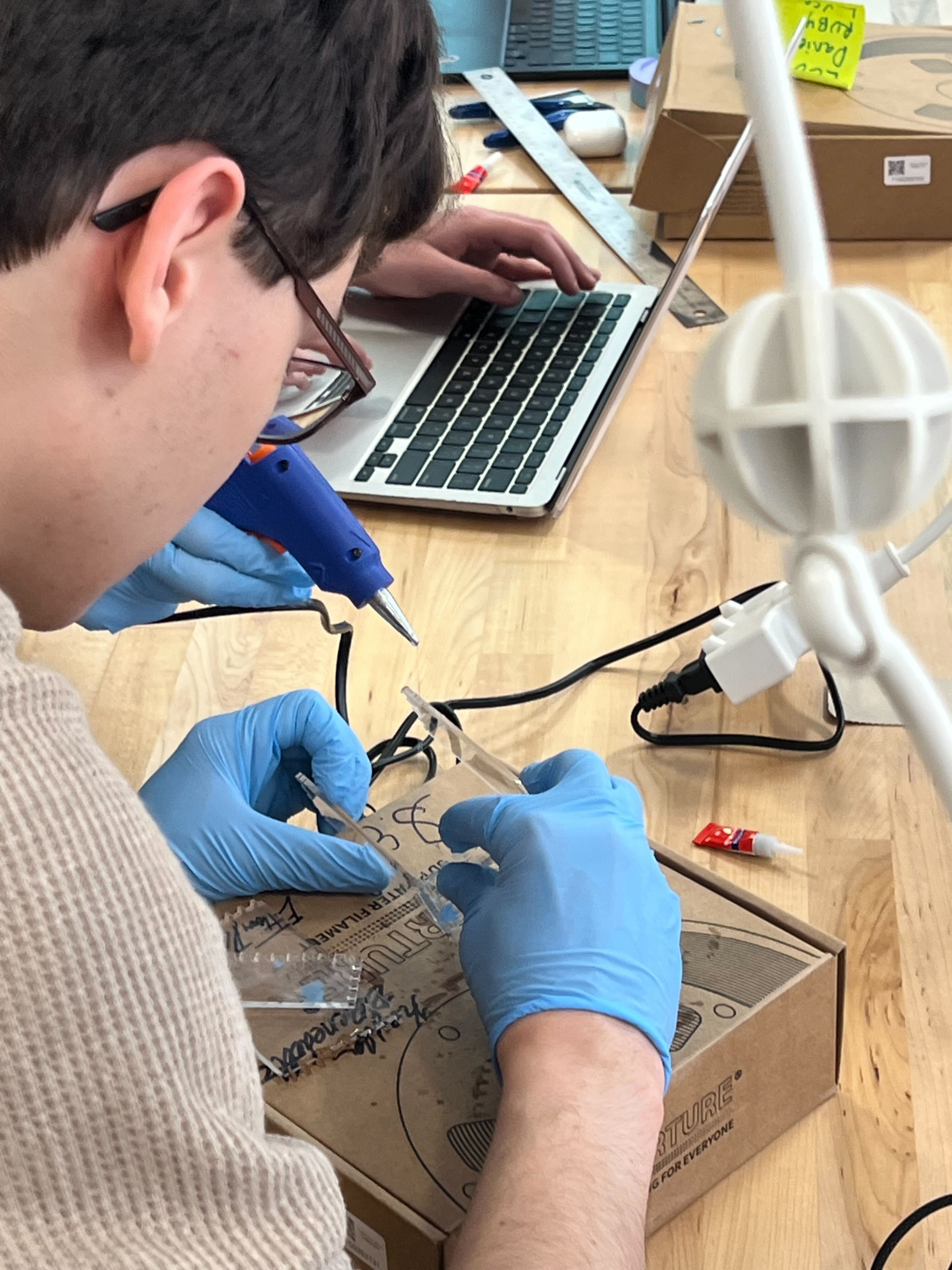
Hot glue proved more effective than superglue due to faster drying times as we did not know about the quick drying spray. In the second iteration, we improved fit around the LEDs and refined component access.
With a classmate’s help, we laser-cut access holes for the battery and switch.
Final version:
Conclusion
This project provided valuable hands-on experience with both additive and subtractive manufacturing techniques. Iterating on the chassis enclosure highlighted the importance of precise measurements, tolerances, and planning ahead to minimize iteration time. While 3D printing allowed for intricate custom shapes, laser cutting provided a faster workflow for structural components. Overall, this experience deepened my understanding of design-for-manufacturing principles and collaborative problem-solving in engineering.
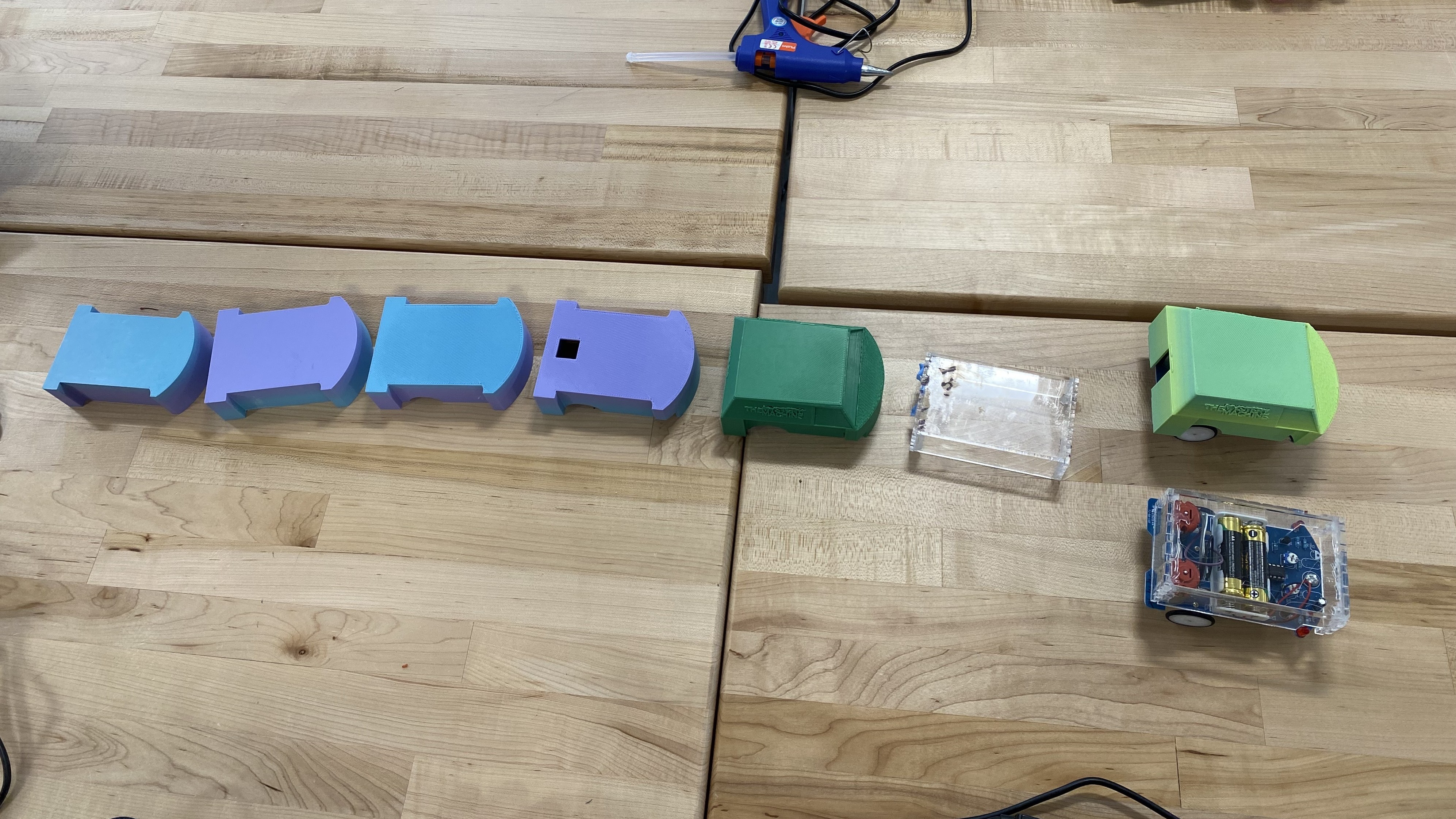
Here is a picture showing all the iterations we did: